Traction machine brake

A machine brake and traction technology, applied in the direction of brake types, mechanical equipment, slack adjusters, etc., can solve the problems of automatic detection of brake loosening gap, time-consuming and cumbersome measurement, difficult operation, etc. The effect of poor measurement accuracy, intelligent measurement and control, and normal operation

Pending Publication Date: 2020-06-23
苏州江南嘉捷光机电技术有限公司
View PDF0 Cites 0 Cited by
  • Summary
  • Abstract
  • Description
  • Claims
  • Application Information

AI Technical Summary

Problems solved by technology

[0002] The brake release gap of the traction machine in the prior art cannot be automatically detected, and it is generally measured manually with a feeler gauge, which is time-consuming and cumbersome, especially difficult to operate at the hoistway installation site, and it is impossible to automatically adjust the push of the electromagnet according to the measured value distance, and then adjust the release gap

Method used


Image

  • Traction machine brake
  • Traction machine brake

Examples


Embodiment Construction

[0022] In order to enable those skilled in the art to better understand the technical solutions of the present invention, the technical solutions in the embodiments of the present invention will be clearly and completely described below in conjunction with the drawings in the embodiments of the present invention. Obviously, the described implementation Examples are only some of the embodiments of the present invention, not all of them. Based on the embodiments of the present invention, all other embodiments obtained by persons of ordinary skill in the art without making creative efforts shall fall within the protection scope of the present invention.

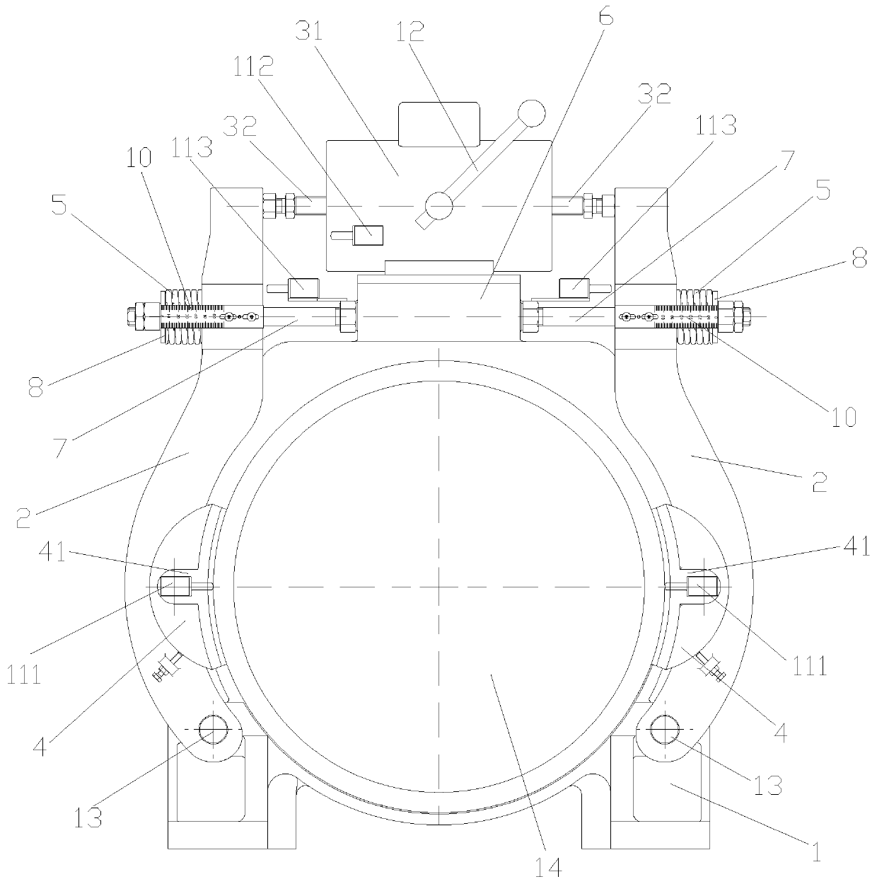
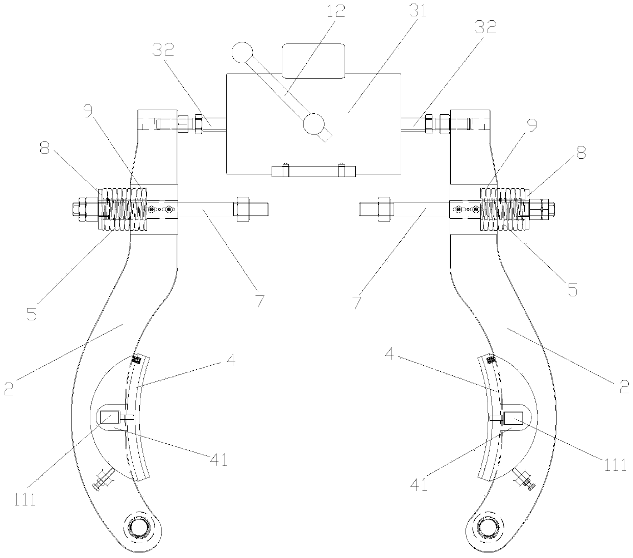
[0023] Such as figure 1 and figure 2 As shown, the traction machine brake of this embodiment includes a base 1, a main shaft 14, a control device, a displacement measuring device, a brake arm 2 rotatably arranged on the base 1, and is used to push the brake arm 2 away from the machine base. The release device of the base 1 an...


PUM


Abstract

The invention discloses a traction machine brake. The traction machine brake comprises a brake state and a brake release state, wherein in the brake state, brake shoes make complete contact with brakesurfaces, and in the brake release state, the brake shoes are completely separated from the brake surfaces; the traction machine brake further comprises displacement measuring devices, the displacement measuring devices comprise first displacement sensors arranged on brake arms, the first displacement sensors are used for measuring the real-time brake release distances between the brake shoes andthe brake surfaces, the first displacement sensors are connected with control devices, and the first displacement sensors transmit the real-time brake release distances between the brake shoes and the brake surfaces in the brake release state to the control devices; and preset modules and comparison modules are arranged in the control devices, the minimum brake release distances between the brakeshoes and the brake surfaces are preset in the preset modules, the comparison modules are used for comparing the real-time brake release distances with the minimum brake release distances, and the control devices control brake release devices to act according to comparison results.

Description

technical field [0001] The invention relates to the technical field of elevators, in particular to a traction machine brake. Background technique [0002] The brake release gap of the traction machine in the prior art cannot be automatically detected, and it is generally measured manually with a feeler gauge, which is time-consuming and cumbersome, especially difficult to operate at the hoistway installation site, and it is impossible to automatically adjust the push of the electromagnet according to the measured value distance, and then adjust the release clearance. Contents of the invention [0003] In view of this, in order to overcome the defects of the prior art, the object of the present invention is to provide an improved traction machine brake, which can automatically adjust the moving distance of the push rod according to the brake release clearance. [0004] In order to achieve the above object, the present invention adopts the following technical solutions: ...

Claims


Application Information

Patent Timeline
Patent Type & Authority Applications(China)
IPC IPC(8): B66D5/08B66D5/30F16D65/62F16D66/00
CPCB66D5/08B66D5/30F16D65/62F16D66/00F16D2066/003
Inventor 刘凡朱耀寿育
Owner 苏州江南嘉捷光机电技术有限公司
Why Eureka
Try Eureka