Eureka AIR delivers breakthrough ideas for toughest innovation challenges, trusted by R&D personnel around the world.

Joint inversion method based on magnetotelluric and direct current resistivity data

A DC resistance and magnetotelluric technology, which is applied in electric/magnetic exploration, electromagnetic wave detection, sound wave reradiation, etc., can solve the problem of affecting the accuracy of forward modeling, reducing the accuracy of inversion results, and increasing the number of grid cells. question

Active Publication Date: 2020-06-23
EAST CHINA UNIV OF TECH
View PDF2 Cites 18 Cited by
  • Summary
  • Abstract
  • Description
  • Claims
  • Application Information

AI Technical Summary

Problems solved by technology

In addition, most of the traditional joint inversion methods are carried out under a fixed forward and inversion grid, which brings extreme instability to data interpretation
This is because a high-precision forward modeling algorithm is a prerequisite for inversion. Obtaining high-precision forward modeling results will inevitably increase the grid density, which will lead to a sharp increase in the number of grid cells for inversion, thus aggravating the inversion. Secondly, if the density of the inversion grid is reduced to reduce the multi-solution of the inversion, it will inevitably affect the accuracy of the forward modeling solution, thereby affecting the accuracy of the inversion results
Therefore, in the traditional joint inversion method, a fixed forward and inversion grid is selected. If the set grid density is low, the accuracy of the inversion results will be reduced, and if the set grid density is too high, the inversion will be aggravated. The multi-solution, how to obtain the appropriate grid density is urgent to study

Method used


Image

  • Joint inversion method based on magnetotelluric and direct current resistivity data
  • Joint inversion method based on magnetotelluric and direct current resistivity data
  • Joint inversion method based on magnetotelluric and direct current resistivity data

Examples


Embodiment Construction

[0057] The present invention will be further described below in conjunction with examples.

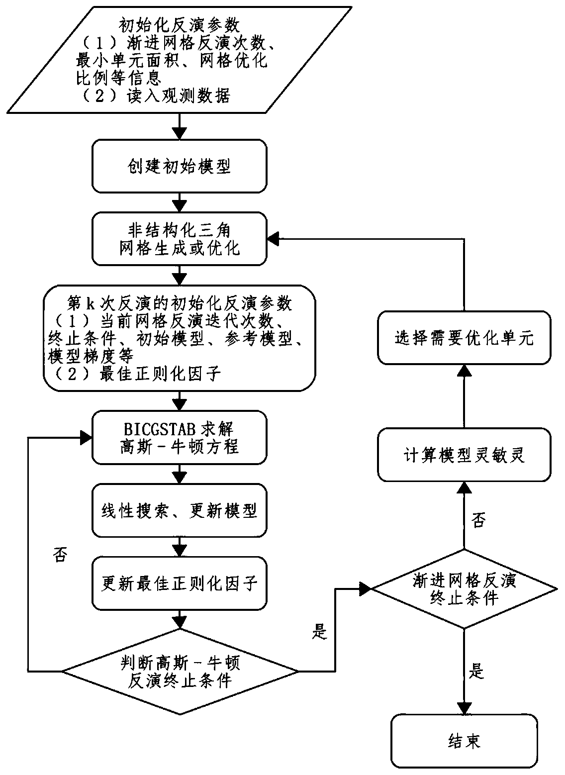
[0058] A joint inversion method based on magnetotelluric and DC resistivity data provided by the present invention realizes the progressive grid inversion technology, and the inversion proceeds step by step from coarse grid to fine grid, effectively and accurately realizing self-adaptive Grid division to obtain appropriate grid density, thereby reducing the multi-solution of inversion and improving the accuracy of inversion results. Among them, the resistivity can be calculated according to the inversion parameter vector obtained after the inversion.

[0059] First, according to the ill-conditioned nature of geophysical inverse problems, construct the objective function of regularized inversion for:

[0060]

[0061] In the formula: m is the inversion parameter vector, d obs is the inversion data vector, μ is the regularization factor; is the data error function; is the mode...


PUM


Abstract

The invention discloses a joint inversion method based on magnetotelluric and DC resistivity data, and the method comprises the steps: determining an inversion region according to observation data, carrying out the subdivision to obtain an initial grid, and setting an initial value of an inversion parameter vector; performing Gaussian-Newton inversion iteration based on the current value of the inversion parameter vector to calculate a model change amount and a linear search step length, and then calculating an iterative update value of the inversion parameter vector; judging whether an inversion termination condition is met or not, and if not, carrying out next iteration; if so, judging whether a progressive grid inversion termination condition is reached or not, and if so, ending the inversion; and if not, carrying out refined subdivision on the grid cell, updating the inversion parameter vector value, and returning to carry out Gauss-Newton inversion iteration until inversion is finished. According to the invention, a joint inversion technology of inversion grid adaptive adjustment is researched and developed, the problem of multiplicity of solutions of joint inversion interpretation of a magnetotelluric method and direct current resistivity data is effectively reduced, and the joint interpretation accuracy is improved.

Description

technical field [0001] The invention relates to the field of applied geophysics, in particular to a joint inversion method based on magnetotelluric and DC resistivity data. Background technique [0002] In the field of applied geophysical exploration, magnetotelluric method (MT) and direct current resistance method (DC) are widely used in mineral resource exploration, and the application effect is remarkable. However, the single magnetotelluric method or DC resistance method can hardly avoid the problem of multi-solution inversion, which affects the accuracy of data interpretation, and thus the joint inversion interpretation technology is derived. Joint inversion can effectively reduce the ambiguity of inversion and improve the accuracy and reliability of data interpretation. In addition, most of the traditional joint inversion methods are carried out under a fixed forward and inversion grid, which brings extreme instability to data interpretation. This is because a high-p...

Claims


Application Information

Patent Timeline
IPC IPC(8): G01V3/12G01V3/00
CPCG01V3/00G01V3/12
Inventor 李曼张志勇蓝泽鸾周峰
Owner EAST CHINA UNIV OF TECH
Why Eureka
Eureka Blog
Learn More