
Radio frequency test method, system and device

A radio frequency test system and radio frequency test technology, applied in transmitter monitoring, receiver monitoring, etc., can solve the problems of not being able to guarantee 100% radio frequency functions, regular maintenance cannot be well guaranteed, and module radio frequency testing cannot be known, etc., to achieve Facilitate production line operations, prevent errors, and reduce data anomalies

Active Publication Date: 2020-06-23
HANGZHOU TUYA INFORMATION TECH CO LTD
View PDF7 Cites 3 Cited by
  • Summary
  • Abstract
  • Description
  • Claims
  • Application Information

AI Technical Summary

Problems solved by technology

[0003] The current test mode can meet the needs of factory batch testing, but for detailed statistics of test results, and when an independent module has a small amount of information, it is impossible to know whether the module has passed the RF test
At the same time, for manually modifying the configuration file of the test instrument, high reliability cannot be achieved. In the case of a large number of instruments, there is a situation of missing configuration.
Some standard parameters of the instrument, line loss and other regular maintenance cannot be well guaranteed
The combination of the above factors and the test results cannot 100% guarantee that the radio frequency function is free from defects.

Method used


Image

  • Radio frequency test method, system and device
  • Radio frequency test method, system and device
  • Radio frequency test method, system and device

Examples


Embodiment Construction

[0037] In order to understand the above-mentioned purpose, features and advantages of the present invention more clearly, the present invention will be further described in detail below in conjunction with the accompanying drawings and specific embodiments. It should be noted that, in the case of no conflict, the embodiments of the present invention and the features in the embodiments can be combined with each other.

[0038] In the following description, many specific details are set forth in order to fully understand the present invention, but the present invention can also be implemented in other ways different from those described here, therefore, the protection scope of the present invention is not limited to the specific details disclosed below. EXAMPLE LIMITATIONS.

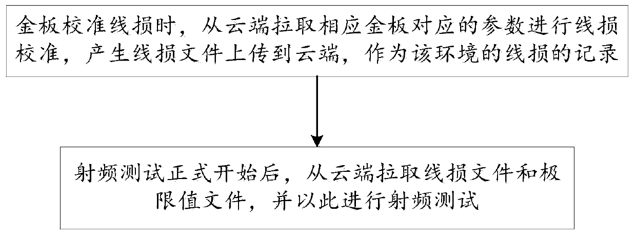
[0039] Such as figure 1 Shown, the embodiment of the present invention discloses a kind of radio frequency testing method, comprises the following steps:

[0040] When calibrating the line loss of the gol...

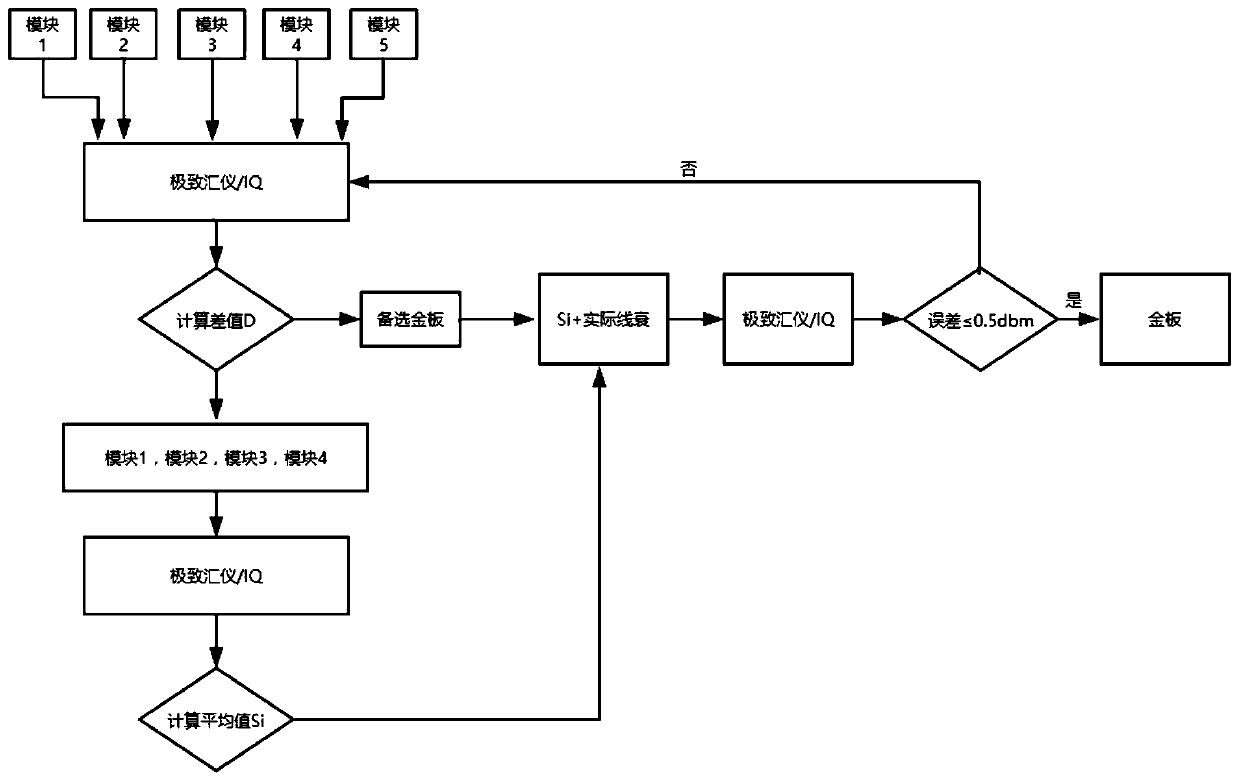

PUM


Abstract

The invention relates to the field of testing of communication equipment, in particular to a radio frequency testing method, system and device. A radio frequency test method comprises the following steps that when a gold plate calibrates line loss, parameters corresponding to the corresponding gold plate are pulled from a cloud end for line loss calibration, and a line loss file is generated and uploaded to the cloud end to serve as a record of the line loss of the environment; and after the radio frequency test is formally started, pulling the line loss file and the limit value file from thecloud, and carrying out the radio frequency test. According to the method provided by the invention, the radio frequency test time is optimized, the test time of a single BK7231S module in an originalfactory is reduced from more than 25 seconds to 12 seconds, and the occupied time of an instrument is reduced by more than half; files in the testing process do not support local modification, so that the preciseness of radio frequency testing and the safety of data are ensured; the time cost and the labor cost of a factory production line are reduced, and the performance of batch module radio frequency test is ensured; therefore, the flow of a factory production line is more standard, reasonable and effective.

Description

technical field [0001] The invention relates to the field of testing of communication equipment, in particular to a radio frequency testing method and its system and device. Background technique [0002] At present, the RF test of the factory production line is generally carried out by instruments. The test solutions provided by mainstream RF instrument manufacturers such as litepoint and Jihuiyi, the RF test time of a single BK7231S module is greater than 25 seconds. At the same time, before performing radio frequency testing, line loss calibration is required, that is, the power loss caused by the test environment and instruments. Formal testing needs to subsidize this loss into the line loop. Different from the R&D experiment environment, a test instrument in the factory is connected to a corresponding number of fixtures and tested independently using the control software provided by the instrument manufacturer. The test log reflects the test results in detail. However...

Claims

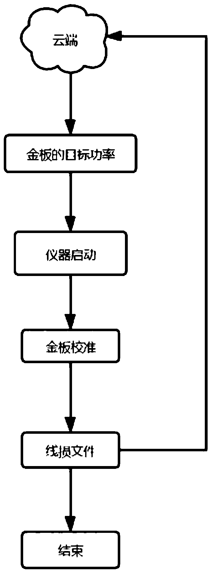

Application Information

Patent Timeline
IPC IPC(8): H04B17/15H04B17/29
CPCH04B17/15H04B17/29
Inventor 毕行健刘峰
Owner HANGZHOU TUYA INFORMATION TECH CO LTD
Learn More