
Roller type motor

A motor and roller technology, applied in the field of roller motors, can solve the problems of high difficulty, high production cost, low efficiency and yield rate, etc.

Inactive Publication Date: 2021-05-14
湖南新视电子技术有限公司
View PDF9 Cites 0 Cited by
  • Summary
  • Abstract
  • Description
  • Claims
  • Application Information

AI Technical Summary

Problems solved by technology

[0003] Compared with the ordinary coil winding process, winding on such a small non-metallic part with complex structural features is more difficult, and the efficiency and yield are not high, so winding is a major problem in the motor industry. The production cost is also higher

Method used

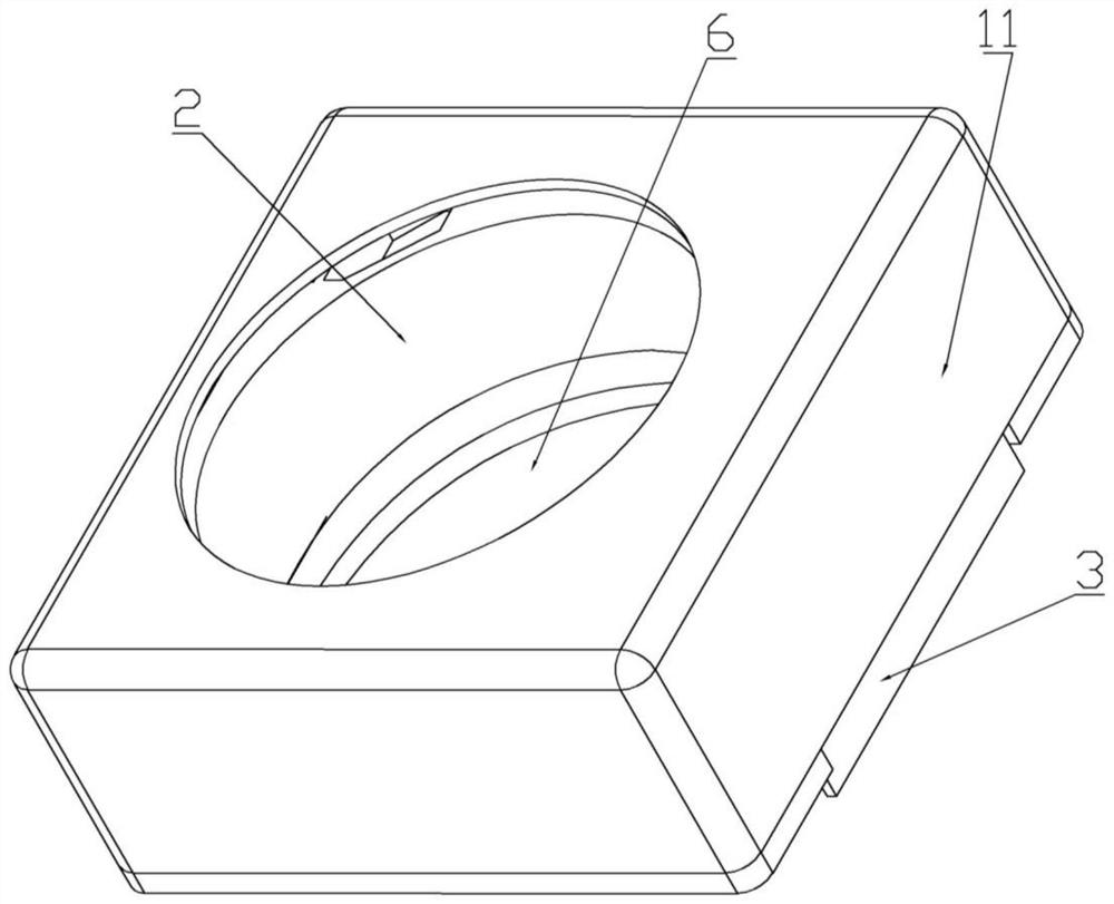
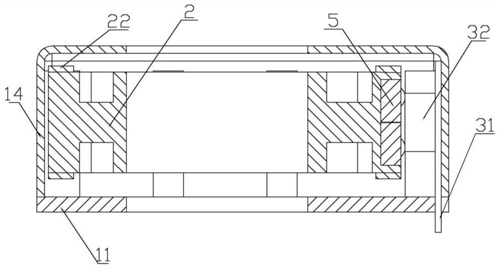
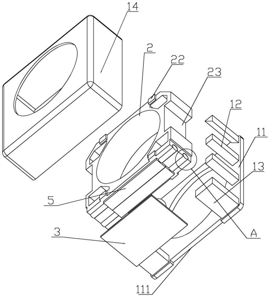

Image

  • Roller type motor
  • Roller type motor
  • Roller type motor

Examples


Embodiment Construction

[0025] The following will clearly and completely describe the technical solutions in the embodiments of the present invention with reference to the accompanying drawings in the embodiments of the present invention. Obviously, the described embodiments are only some, not all, embodiments of the present invention. Based on the embodiments of the present invention, all other embodiments obtained by persons of ordinary skill in the art without making creative efforts belong to the protection scope of the present invention.

[0026] In the description of the present invention, it should be understood that the orientations or positional relationships indicated by "front", "rear", "left", "right", "upper" and "lower" in terms are based on those shown in the accompanying drawings. Orientation or positional relationship is only for the convenience of describing the present invention and simplifying the description, and does not indicate or imply that the referred device or element must ...


PUM


Abstract

The invention discloses a roller type motor which comprises a fixed module, a moving module and a coil module. A winding process is simplified, winding efficiency and a yield are improved, an elastic sheet and a welding process are omitted, a manufacturing process is optimized, the design of a production mold is simplified, the production cost is reduced, and the productivity is improved. And the competitiveness of the product in the industry is increased.

Description

technical field [0001] The invention relates to the technical field of voice coil motors, in particular to a roller motor. Background technique [0002] Voice coil motor (Voice Coil Actuator), is a device that converts electrical energy into mechanical energy, and realizes linear and limited swing angle movement. In the prior art, the mirror holder is produced first, and then the copper wire is wound in a large The wire is wound on the column to form a certain number of coils. The winding of the small winding column is to form a welding position in order to conduct with the lower shrapnel to form a loop. The cross-wire is to conduct the symmetrical coil on the other side to form a complete pair of coils. After the loop is completed, there will be a pair of coils and a pair of welding positions. [0003] Compared with the ordinary coil winding process, winding on such a small non-metallic part with complex structural features is more difficult, and the efficiency and yield a...

Claims


Application Information

Patent Timeline
IPC IPC(8): H02K33/18
CPCH02K33/18
Inventor 吴浩陈立虎车亮孙朋林唐剑
Owner 湖南新视电子技术有限公司
Learn More