Deceleration separation device

A separation device and deceleration parachute technology, which is applied in the field of drones, can solve the problems of relatively high cost, interference between deceleration parachute and blades, poor deceleration effect, etc., and achieve the effect of reducing overload impact and improving reliability

Pending Publication Date: 2020-06-26
BEIJING ZHZ TECH
View PDF0 Cites 3 Cited by
  • Summary
  • Abstract
  • Description
  • Claims
  • Application Information

AI Technical Summary

Problems solved by technology

[0002] At present, most recovery deceleration devices for unmanned aerial vehicles are modular single devices such as first-level drogue parachute devices or rear speed brakes. leaf interference, and the rear speed brake is likely to cause additional torque in the deceleration state, and the deceleration effect is not good
In addition, the existing reduction gear does not involve the separation device

Method used


Image

  • Deceleration separation device
  • Deceleration separation device
  • Deceleration separation device

Examples


Embodiment Construction

[0028] The technical solutions in the embodiments of the present invention are clearly and completely described below in conjunction with the accompanying drawings in the embodiments of the present invention. Obviously, the described embodiments are part of the embodiments of the present invention, but not all of them. Based on the embodiments of the present invention, all other embodiments obtained by those skilled in the art without making creative efforts belong to the protection scope of the present invention.

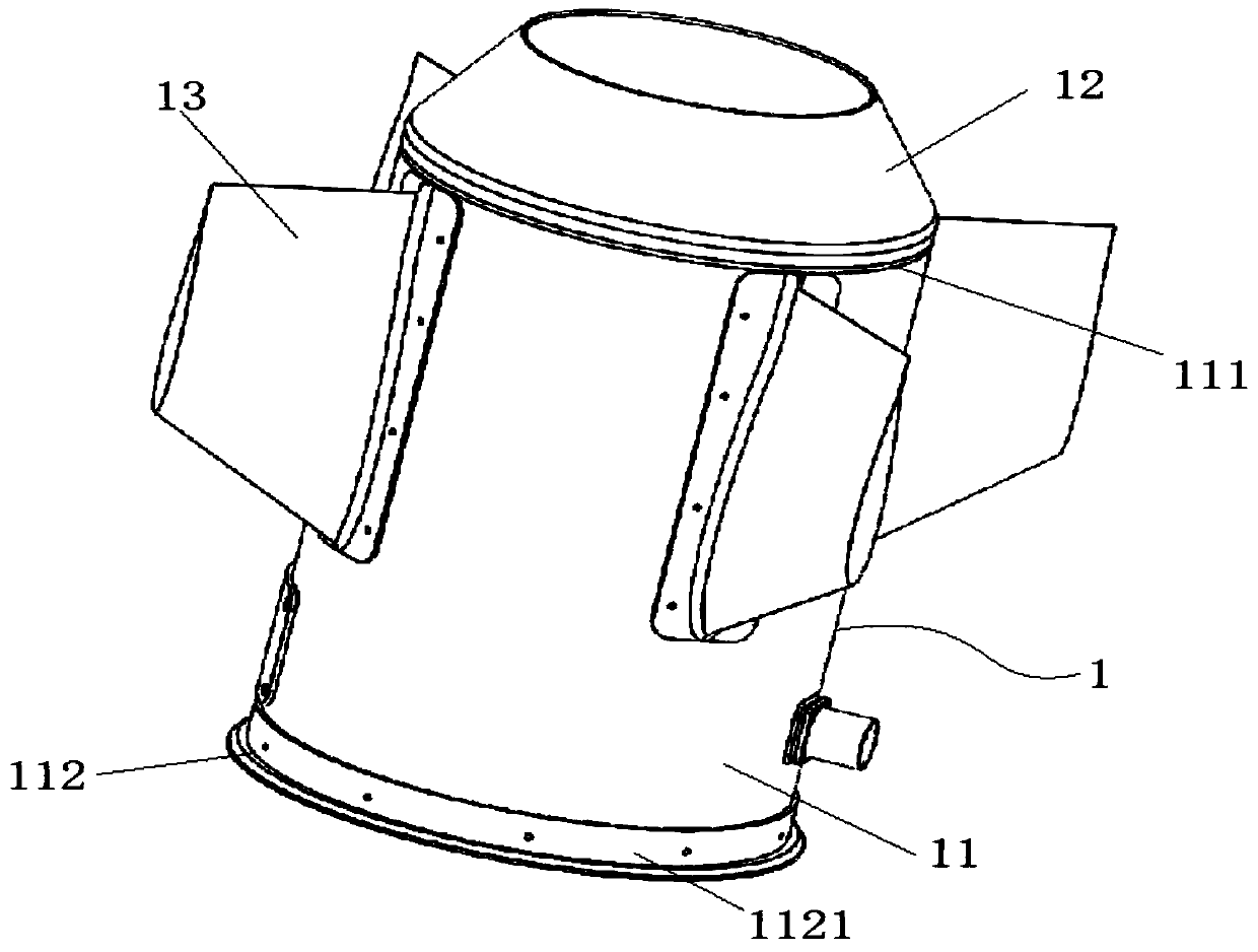
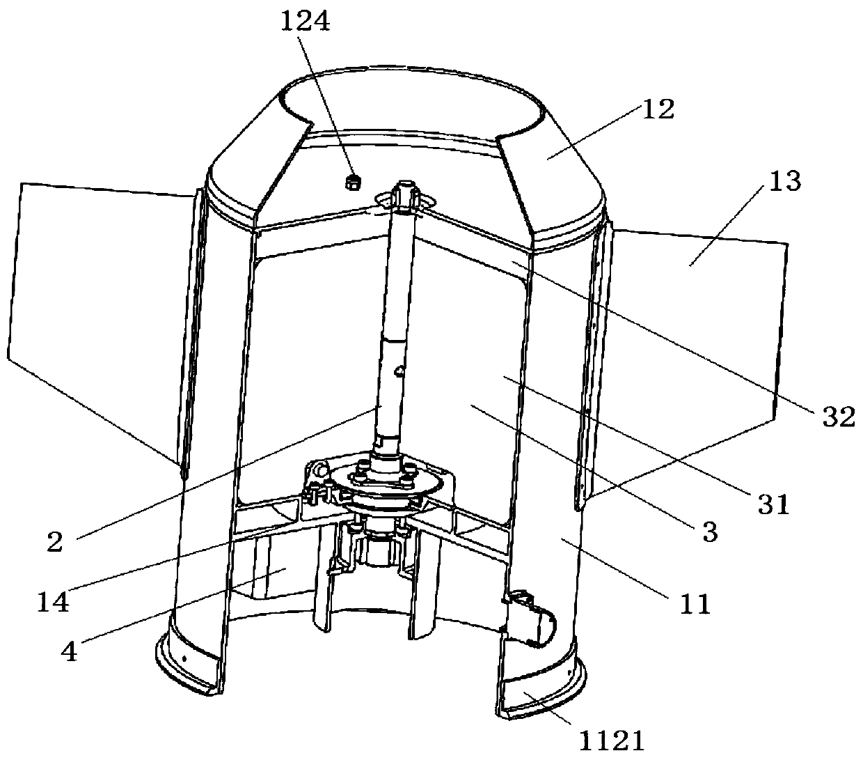
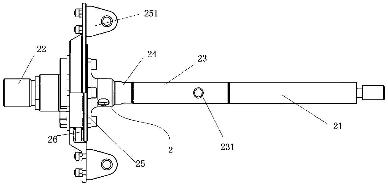
[0029] Such as figure 1 and figure 2 As shown, the present application provides a deceleration separation device, including: a deceleration parachute compartment 1, a combined actuator 2, a deceleration parachute bag 3, a battery box 4 and a sub-machine control board. The drogue canopy 1 includes a canopy main body 11 and a canopy cover 12 . Wherein, the umbrella cabin main body 11 is a composite material, and the umbrella cabin main body 11 is an integral struc...


PUM


Abstract

The invention discloses a deceleration separation device which comprises a deceleration parachute cabin, a combination actuator, a deceleration parachute pack, a battery box and a sub-machine controlpanel. The deceleration parachute bay comprises a parachute bay body and a parachute bay cover; a first port of the parachute bay body is clamped with the parachute bay cover; a second port of the parachute bay body is connected with a sub-aircraft protection cylinder of the unmanned aerial vehicle through a first connecting part; the assembling actuator is fixedly arranged in the parachute bay body; one end of the combined actuator is a parachute throwing device and is connected with the parachute cabin cover; the other end of the combined actuator is an explosive bolt and is connected with atransition joint of the unmanned aerial vehicle; the deceleration parachute pack is arranged in the deceleration parachute cabin and connected with the parachute cabin cover and the assembling actuator through second connecting parts. The battery box is arranged in the parachute bay body and is respectively connected with the parachute throwing device and the explosive bolt; and the sub-machine control panel is arranged in the parachute bay body and is in communication connection with the parachute throwing device and the explosive bolt respectively. The device can be separated from the aircraft, the weight during free flight is reduced, and the cruising ability of the aircraft is improved.

Description

technical field [0001] The present application relates to the technical field of unmanned aerial vehicles, in particular to a deceleration and separation device. Background technique [0002] At present, most recovery deceleration devices for unmanned aerial vehicles are modular single devices such as first-level drogue parachute devices or rear speed brakes. The interference of leaves, and the rear speed brake is likely to cause additional torque when decelerating, and the deceleration effect is not good. In addition, the existing reduction gears do not involve a separation device. Contents of the invention [0003] The purpose of this application is to provide a deceleration separation device, which can effectively separate from the aircraft after realizing the deceleration function, reduce the weight of the aircraft when it is flying freely, and improve the endurance of the aircraft. [0004] In order to achieve the above purpose, the application provides a decelerati...

Claims


Application Information

Patent Timeline
Patent Type & Authority Applications(China)
IPC IPC(8): B64D17/80B64D17/64B64D17/72
CPCB64D17/64B64D17/725B64D17/80
Inventor 梁国强刘杨舜李宪军薛蛟刘东波
Owner BEIJING ZHZ TECH
Why Eureka
Try Eureka