
A small curve radius steel box girder bridge erecting machine and erection construction method

A construction method and technology of steel box girder, applied in the direction of bridge construction, erection/assembly of bridges, bridges, etc., can solve problems such as construction difficulties, and achieve the effects of novel technology, cost reduction, and impact reduction

Active Publication Date: 2022-04-29
THE THIRD ENG CO LTD OF CHINA RAILWAY SEVENTH GRP
View PDF15 Cites 0 Cited by
  • Summary
  • Abstract
  • Description
  • Claims
  • Application Information

AI Technical Summary

Problems solved by technology

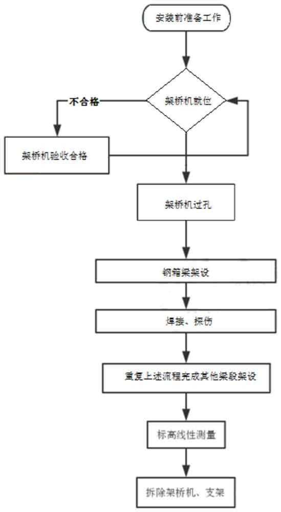
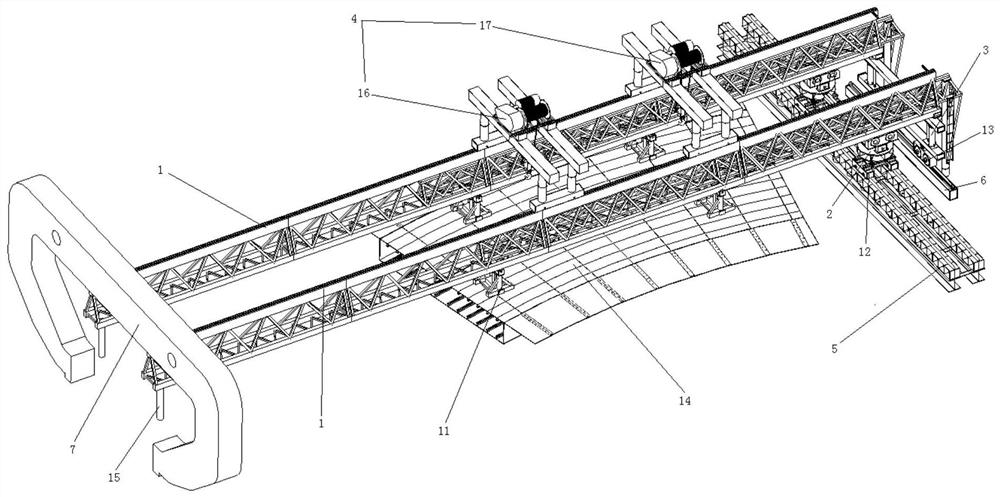
[0004] The purpose of the present invention is to provide a steel box girder bridge erecting machine with a small curve radius and an erection construction method for the problem of difficult construction under the small curve radius of the steel box girder. Construction, safe and reliable, speed up the construction progress

Method used


Image

  • A small curve radius steel box girder bridge erecting machine and erection construction method
  • A small curve radius steel box girder bridge erecting machine and erection construction method
  • A small curve radius steel box girder bridge erecting machine and erection construction method

Examples


Embodiment Construction

[0042] In order to make the object, technical solution and advantages of the present invention clearer, the present invention will be described in further detail below in conjunction with specific embodiments and with reference to the accompanying drawings.

[0043] The present invention is described more fully with respect to certain embodiments with reference to the accompanying drawings, in which some, but not all embodiments are shown. Indeed, various embodiments of the invention may be embodied in many different forms and should not be construed as limited to these set forth embodiments; rather, these embodiments are provided so that this invention will satisfy applicable legal requirements.

[0044] The terms "first", "second", "third", "fourth" and "fifth" are used for descriptive purposes only and are not to be construed as indicating or implying relative importance or implying the indicated technical features quantity. Thus, features defined as "first", "second", "th...


PUM


Abstract

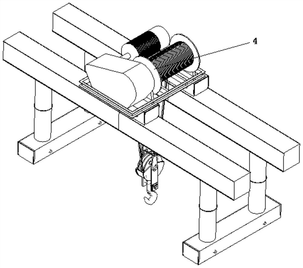
The invention provides a steel box girder bridge erecting machine with a small curve radius and a construction method for erecting it, comprising a main beam of the bridge erecting machine, a front outrigger device arranged at the front end of the main beam of the bridge erecting machine, and a rear outrigger arranged at the rear end of the bridge erecting machine device, the middle outrigger device installed near the rear end of the main girder of the bridge erecting machine, and the middle outrigger traversing track arranged along the transverse bridge direction, the bottom of the middle outrigger device is installed on the middle outrigger traversing track through the middle leg sliding block ; The main girder of the bridge erecting machine is provided with a front crane 16 and a rear crane 17. When the sliding block of the middle outrigger on the moving track moves the middle outrigger, the beam tail of the main girder of the bridge erecting machine will also move accordingly, and the rotation angle of the bridge erecting machine can be adjusted, so that the whole machine of the bridge erecting machine can be adjusted. The posture is adjusted to the erection posture of the steel box girder, so that the steel box girder erected by the bridge erecting machine with this posture is the set steel box girder posture, which is suitable for the erection of small curve radius steel box girders.

Description

technical field [0001] The invention belongs to the technical field of bridge engineering, and in particular relates to a steel box girder erecting machine with small curve radius and an erecting construction method. Background technique [0002] With the rapid development of my country's economy, the number of bridges is also increasing. In order to shorten the construction period of bridges, give full play to the characteristics of materials, and improve economic and social benefits, steel box girder bridges have gradually become one of the important forms of bridge structures. At the same time, due to the environmental complexity, functional diversity, and linear complexity of the steel box girder bridge construction, it has a great impact on the installation and construction of the steel box girder, especially to solve the problem of the steel box girder under the small curve radius. erection problem. [0003] For example, steel box girders are used for the 5th to 7th j...

Claims


Application Information

Patent Timeline
Patent Type & Authority Patents(China)
IPC IPC(8): E01D21/00
CPCE01D21/00
Inventor 田伯科张华韩斌张志跃潘兴良王朝陆兵新王平孝宋忙社张红勇谭鹤龄张品康纪平
Owner THE THIRD ENG CO LTD OF CHINA RAILWAY SEVENTH GRP
Learn More