
Cable erecting device and erecting method

A cable support and cable technology, applied to cable laying equipment, electrical components, etc., can solve the problems of low cable construction efficiency, dependence on labor, and small cable erection space, so as to reduce the repeated rework rate, reduce economic costs, and shorten the construction period. Effect

Active Publication Date: 2021-11-16
SHANGHAI ELECTRIC POWER DESIGN INST +1
View PDF10 Cites 0 Cited by
  • Summary
  • Abstract
  • Description
  • Claims
  • Application Information

AI Technical Summary

Problems solved by technology

Due to the high hardness of the protective layer on the surface of the cable, it is difficult to bend. If the bending radius of the cable exceeds a certain threshold during erection, it will cause serious damage to the cable and affect the safety and durability of the cable operation.
[0003] In the pipe gallery, the connecting position of the jacking pipes at two different elevations needs to be connected by a shaft. If the depth of the shaft is deep, it is necessary to set up a stairway to ensure the safe passage of the inspection personnel. At this time, the space for the installation of the cables is reduced to a small size. In the erection process, there are many reasons such as corners, high drop, and small available space, which force the cable to have complex bending problems.
Even if it is theoretically possible to carry out detailed design and planning, in the process of complex erection construction, the erection requirements can only be met through continuous adjustments on site, which will cause some problems
First, in the actual construction process, the uncertainty will increase, and various problems need to be dealt with on the spot, which will reduce the efficiency of the entire cable erection construction; It can rely on manual labor, and once there is a problem in the actual erection, it is extremely difficult to move the cable
These problems greatly waste the time and labor costs required for cable erection

Method used


Image

  • Cable erecting device and erecting method
  • Cable erecting device and erecting method
  • Cable erecting device and erecting method

Examples


Embodiment 1

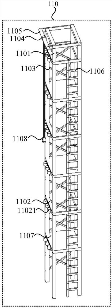
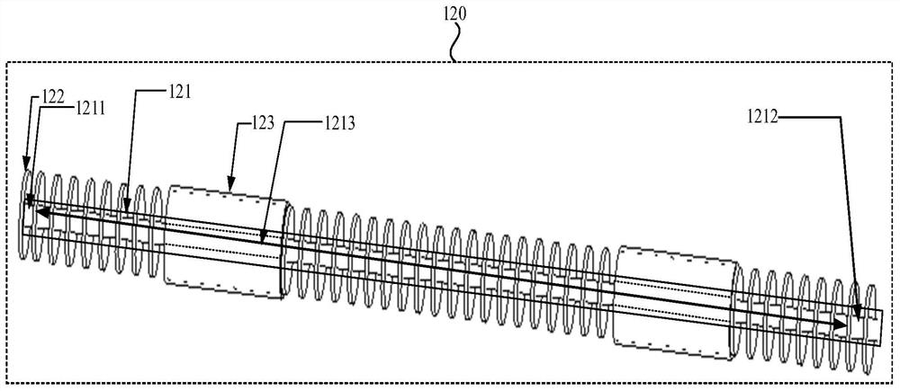
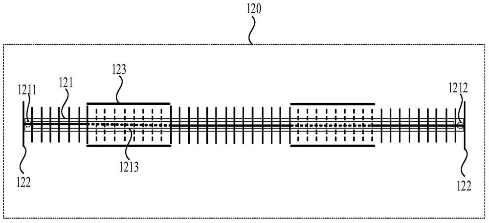
[0030] figure 1 A cable holder according to a first embodiment of the present invention, a schematic view, figure 2 Simulation is a schematic diagram of a cable embodiment of the present invention is provided; means suitable for the erection of the power cable in the utility tunnel complex space, for example, the tube may be complex to set up the position of the shaft of the power cable gallery corner like. refer to figure 1 with figure 2 The erection of cable apparatus comprising: analog cable and cable bracket 110 120; cable holder 110 includes a cable securing device; analog cable 120 includes a center line 121 may be curved, bent panel provided on a plurality of flexible sleeve 122 and the centerline 121 bending control board provided outside the fixed sleeve 123, the control board 122 is bent for limiting the bending of the bending angle of the center line 121; means for fixing the cable 123 is fixed by a fixing sleeve 120 analog cable.

[0031] Wherein the cable securing de...

Embodiment 2

[0052] Figure 5 It is a flow chart of a cable framework method according to the second embodiment of the present invention, and the cable frameworking method provided by the embodiment of the present invention can be achieved by the cable erasure device provided by the above embodiment. like Figure 5 As shown, the cable screening method includes:


PUM


Abstract

The embodiment of the invention discloses a cable erecting device and an erecting method. The cable erecting device comprises a cable support and a simulation cable. The cable support comprises a cable fixing device; the simulation cable comprises a bendable center line, a plurality of bending control plates arranged on the bendable center line and a fixing sleeve arranged on the outer sides of the bending control plates in a sleeving mode, and the bending control plates are used for limiting the bending angle of the bendable center line; the cable fixing device is used for fixing the simulation cable through the fixing sleeve. Compared with the prior art, the arrangement efficiency of the cable support at a special position can be improved, the repeated rework rate caused by a complex erection space is reduced, and the cable is protected in the cable erection process.

Description

Technical field [0001] Embodiments of the present invention relates to the field of power cables stent design, in particular, it relates to an apparatus and method for erecting cable erection. Background technique [0002] In power cables integrated construction design process, the position relates to pipe racks of the branch port, connect at a different elevation top tube or the like, it is easy to complex spatial structure appears, then superimposed utility tunnel itself to consider other conduits, walkways, etc. so that the tube inner gallery space for split cable set different degrees, to bend the path of the cable and thus the occurrence of non-planar. Due to the high hardness of the protective layer surface of the cable, it is difficult to bend, the bending radius of the cable when the erection process exceeds a certain threshold, it will cause serious damage to the cable, the cable affect the operational safety and durability. [0003] The pipe rack in two different elevat...

Claims


Application Information

Patent Timeline
Patent Type & Authority Applications(China)
IPC IPC(8): H02G3/04H02G3/02H02G1/06
CPCH02G3/04H02G3/02H02G1/06
Inventor 蔡洪浩周辉牛婧蓝睿
Owner SHANGHAI ELECTRIC POWER DESIGN INST
Learn More