A tie-down system for prefabricated hanging scaffolding

A scaffolding and assembly technology, applied in the field of tie system, can solve problems such as uneconomical, unfavorable, and hidden dangers, and achieve the effects of cost saving, reasonable structure, and reasonable force

Active Publication Date: 2021-12-03
淮安市博彦土木工程科学研究院有限公司
View PDF10 Cites 0 Cited by
  • Summary
  • Abstract
  • Description
  • Claims
  • Application Information

AI Technical Summary

Problems solved by technology

[0004] However, with the rise of prefabricated buildings, there will be many discomforts when using traditional cantilevered scaffolding, so a new type of suspension scaffolding with pull-up rods has emerged. The general idea of ​​this suspension scaffolding is to weld one end of the steel beam. Open a hole behind the end plate and use high-strength bolts to anchor it on the structural side beam or wall column, hang the other end of the steel beam on a steel bar to hang on the side beam or wall column of the upper structure
However, there are indeed many problems in its specific common practice. For example, the upper end of the steel tie rod is welded with a single piece of bent steel plate and then hung on the outside of the side beam of the superstructure with bolts. The knot angles are inconsistent, which will cause the steel wire rope or steel tie rod to be affected by the inclined steel plate and cannot fully tension the cantilever beam, resulting in the inability to effectively bear force and pose a great safety hazard; the position of the steel tie rod conflicts with the inner row of the scaffold, so Installing the steel tie rods off-center and not on the same axis as the steel beams will cause the steel beams to be pulled laterally on the plane and generate secondary bending moments. At the same time, the stress on the bolted joints between the inner ends of the steel beams and the structural edge beams will be more unfavorable. Great potential safety hazard; the lengths of steel tie rods in different parts of the same building are different, and the lengths of tie rods in different buildings are even more different. In common practice, each position is processed separately according to the actual length required on site. Unable to achieve universal turnover, so it is seriously uneconomical, and also adds a lot of cost to procurement and storage

Method used


Image

  • A tie-down system for prefabricated hanging scaffolding
  • A tie-down system for prefabricated hanging scaffolding
  • A tie-down system for prefabricated hanging scaffolding

Examples


Embodiment 1

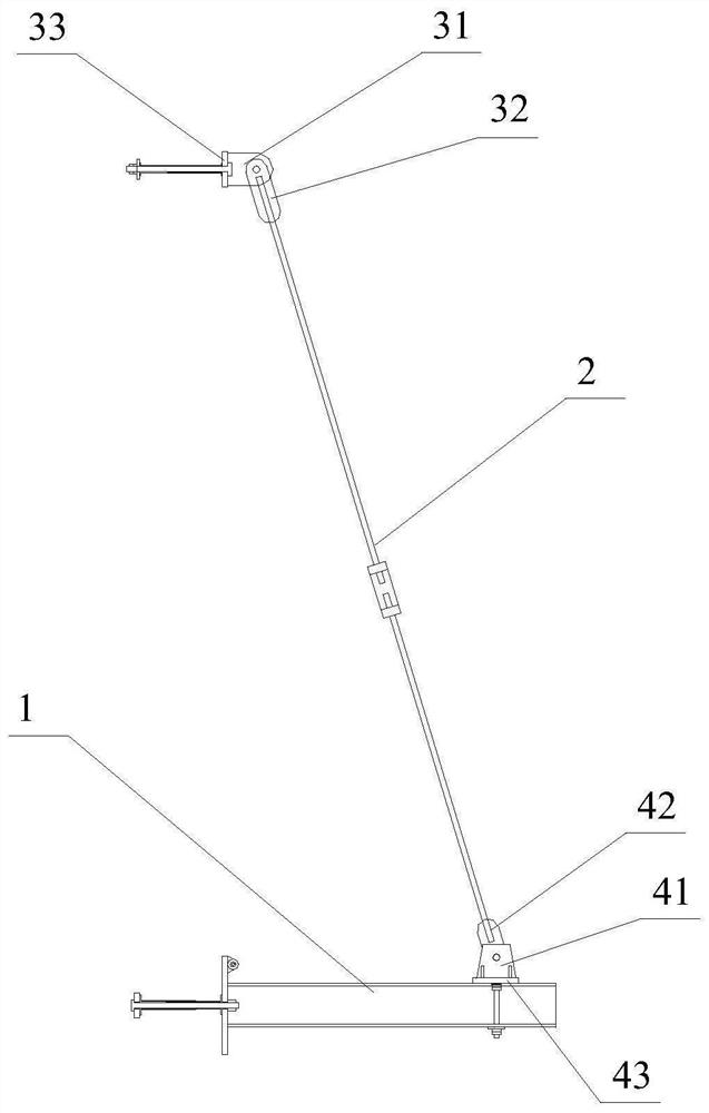
[0037] Embodiment 1: A tie-knot system for an assembled suspended scaffold, including several cantilevered beams 1 and a scaffold erected on the cantilevered beams 1 .

[0038] The length of the cantilever beam 1 protruding from the outer wall of the building is less than 1.8 meters, and a steel tie rod 2 is set on the cantilever beam 1 to connect the outer end of the cantilever beam 1 with the structural beam of the superstructure. The upper end of the reinforcement rod 2 is connected with the superstructure beam through the upper connection assembly 3, and the lower end is connected with the cantilever beam 1 through the lower connection assembly 4, and the reinforcement rod 2 is provided with turnbuckle bolts. The lower connection assembly 4 of the suspension assembly is located on the inner side of the outer pole of the scaffold erected on the cantilever beam 1 .

[0039] The upper connection assembly 3 includes an upper clamping plate group 31, an upper fixing plate 33 an...

Embodiment 2

[0041] Embodiment 2: A tie-knot system for an assembled suspended scaffold, including several cantilevered beams 1 and a scaffold erected on the cantilevered beams 1 .

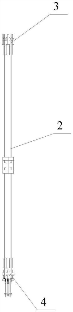
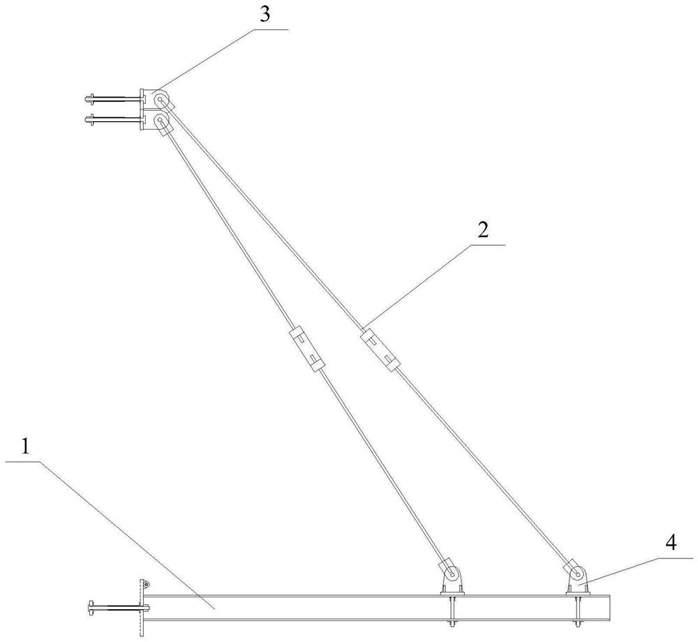
[0042] The difference from Embodiment 1 is that in this embodiment, if the length protruding from the outer wall of the building is greater than or equal to 1.8 meters and less than 3 meters, two reinforcement rods 2 are arranged on the cantilever beam 1 .

[0043] A set of upper connecting components 3 and a lower connecting component 4 are arranged at the upper and lower ends of the two reinforcement rods 2 respectively, wherein the two sets of connecting components at the upper end are distributed up and down, and the two sets of connecting components at the lower end are respectively located on the scaffolding erected on the cantilever beam 1 The inner side of the inner pole and the outer pole. The upper connection assembly 3 arranged at the lower part of the superstructure structural beam and the lower co...

Embodiment 3

[0045] Embodiment 3: A tie-knot system for an assembled suspended scaffold. In this embodiment, the length of the cantilever beam 1 protruding from the outer wall of the building is less than 1.8 meters. Reinforced tie rods 2 tied to the structural beams of the superstructure.

[0046] The difference is that the upper splint group 31 and the lower splint group 41 of the upper connection assembly 3 and the lower connection assembly 4 of the suspension assembly are all single-group double splint structures, and an upper connection plate 32 is respectively fixed on the two splints of the upper splint group 31, The two upper connecting plates 32 are respectively connected with an upper reinforcing bar tie rod 2, the two splints of the lower splint group 41 jointly clamp the lower connecting plate 42, the lower connecting plate 42 is connected with the lower reinforcing bar tie rod 2, and the lower ends of the two upper reinforcing bar tie rods 2 pass through the connector 6 is con...


PUM


Abstract

The invention discloses a knotting system for an assembled suspended scaffold, which includes several cantilevered beams and scaffolds erected on the cantilevered beams, each cantilevered beam is obliquely provided with steel tie rods for tying the outer ends of the cantilevered beams to the superstructure structural beams ; The upper end of the reinforcement rod is connected to the superstructure beam through the upper connection assembly, and the lower end is connected to the cantilever beam through the lower connection assembly, and the reinforcement rod is provided with a turnbuckle bolt. In the knot-tying system of the assembled suspended scaffolding of the present invention, steel bar tie rods are arranged on each cantilever beam to tie the knot with the structural beam of the superstructure, so as to ensure the stable connection of the cantilever beam.

Description

technical field [0001] The invention belongs to the field of building construction, and in particular relates to a tie system for hanging scaffolding. Background technique [0002] Cantilevered scaffolding is a simple facility used in construction. The erection method is to divide the full-height scaffolding into several sections. Scaffolding can be erected by using this method. Scaffolding over 50m can be erected, and the facade of the cantilevered scaffolding must be fully equipped with scissors. [0003] The common traditional method of cantilevered scaffolding is to tile the cantilevered section of the cantilevered steel beam and anchor it on the floor surface, and the cantilevered section is extended as the pole foundation for scaffolding. The length of the anchored section is not less than 1.25 times that of the cantilevered section. The whole process from the beginning of erection to the completion of the mission only considers the force of the cantilevered steel bea...

Claims


Application Information

Patent Timeline
Patent Type & Authority Patents(China)
IPC IPC(8): E04G5/04E04G5/00E04G3/20
CPCE04G3/20E04G5/006E04G5/046
Inventor 陈胜陈辉
Owner 淮安市博彦土木工程科学研究院有限公司
Why Eureka
Try Eureka