Claw for movably clawing temperature measurement probe in metallurgical industry

A technology of temperature measuring probes and claws, which is applied in the field of metallurgical robots, can solve the problems of unstable assembly of temperature measuring guns and temperature measuring probes, low installation efficiency, and high risk factor of temperature measuring probes, and achieve labor-saving and compact structure. Simple and compact, stable and reliable effect

Inactive Publication Date: 2019-06-11
HARBIN INST OF TECH
View PDF12 Cites 3 Cited by
  • Summary
  • Abstract
  • Description
  • Claims
  • Application Information

AI Technical Summary

Problems solved by technology

[0003] In order to solve the problem of high risk factor and low installation efficiency of the existing manual assembly temperature measuring probe, and at the same time realize the unstable assembly of the temperature measuring gun and the temperature measuring probe in the automatic temperature measurement work, the present invention further proposes a mobile Grab the claws of the temperature probe

Method used


Image

  • Claw for movably clawing temperature measurement probe in metallurgical industry
  • Claw for movably clawing temperature measurement probe in metallurgical industry
  • Claw for movably clawing temperature measurement probe in metallurgical industry

Examples


specific Embodiment approach 1

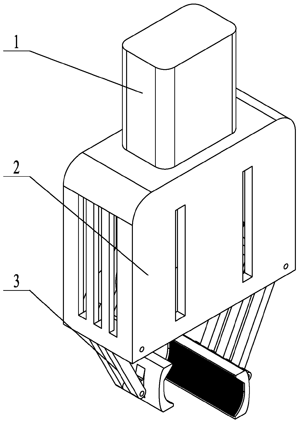
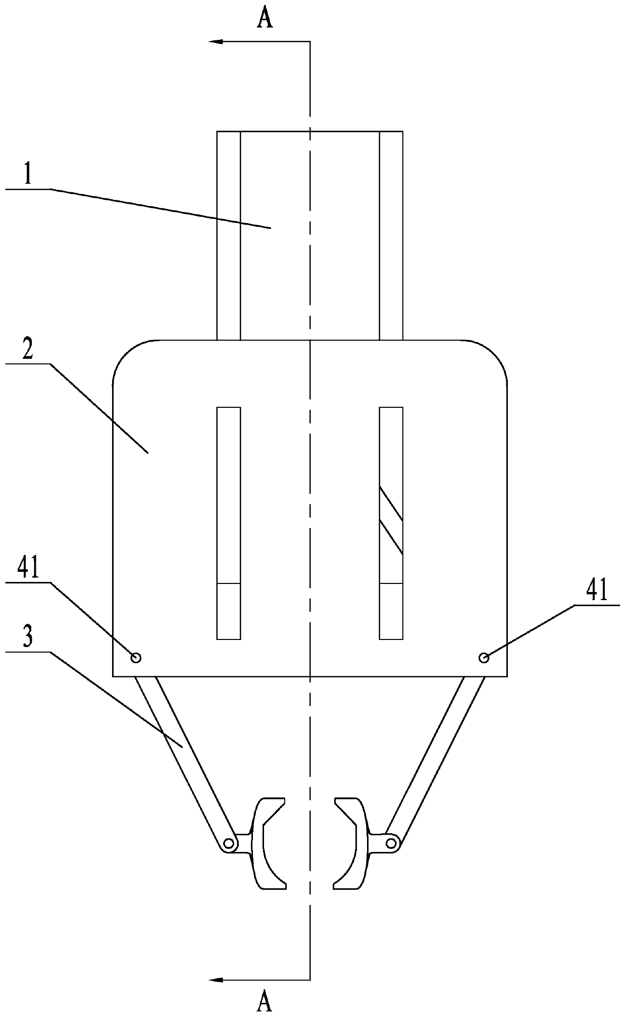
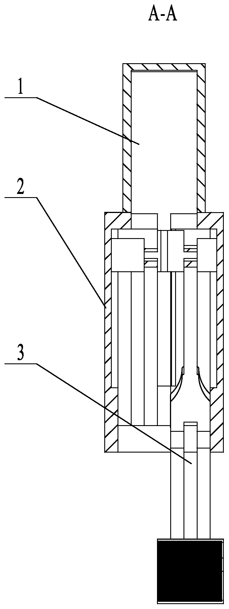
[0032] Specific implementation mode one: combine Figure 1 to Figure 21 Describe this embodiment. A claw used in this embodiment to move and grab a temperature measuring probe in the metallurgical industry includes a cylinder drive mechanism 1, a fixed bracket 2, and a mechanical jaw actuator 3. The cylinder drive mechanism 1 is set on the fixed bracket 2. On the upper end face of the top, the piston rod of the cylinder driving mechanism 1 is fixedly connected with an intermediate connecting slide block 33, and the lower end face of the fixed support 2 top is symmetrically and vertically fixedly connected with two slider guide rails 21, and the left and right sides of the middle connecting slide block 33 The ends are respectively set on the slider guide rail 21 and perform linear reciprocating motion along the height direction of the slider guide rail 21. The middle part of the middle connecting slider 33 is vertically fixed with a rotating connecting rod 45, and the mechanical...

specific Embodiment approach 2

[0038] Specific implementation mode two: combination Figure 1 to Figure 12 Describe this embodiment, the intermediate connecting slider 33 in this embodiment is set on the middle part of the rotating connecting rod 45, the left rotating arm 37 is set on the rear end of the rotating connecting rod 45, and the right rotating arm 31 is set on the front end of the rotating connecting rod 45 , the length of the right clamping plate 35 is greater than the length of the left clamping plate 36, and the front edge of the left clamping plate 36 is at the front side of the rear end edge of the right clamping plate 35. The undisclosed technical features in this embodiment are the same as those in the first embodiment.

[0039]In order to ensure the accuracy of the entire clamping operation, and to realize the anti-overturning characteristics in the clamping process, a left clamping plate 36 and a right clamping plate 35 are arranged in the opposite direction on the inner side of the end ...

specific Embodiment approach 3

[0041] Specific implementation mode three: combination Figure 1 to Figure 10 and Figure 19 To illustrate this embodiment, the front and rear ends of the rotating connecting rod 45 described in this embodiment are respectively provided with limiting blocks 32, and the middle parts of the front and rear vertical end surfaces of the fixed bracket 2 are respectively provided with chute 22, and each limiting block 32 They are respectively clamped in a chute 22 and perform linear reciprocating motion along the height direction of the chute 22 . The undisclosed technical features in this embodiment are the same as those in the first or second specific embodiment.

[0042] Rotate the stoppers 32 at the front and rear ends of the connecting rod 45 to limit its motion plane, so as to ensure that the swivel arm is always on the same plane during the motion process, so as to reduce the occurrence of the left and right swivel arms during the swivel motion. The possibility of vibration ...


PUM


Abstract

The invention discloses a claw for movably clawing a temperature measurement probe in the metallurgical industry, which is related to the technical field of a metallurgical robot, and is used for solving a problem of high danger coefficient and poor mounting efficiency in existing manual assembling of the temperature measurement probe and instability in implementation of assembling a temperature measurement gun and the temperature measurement probe in an automatic temperature measurement work. The claw comprises an air cylinder driving mechanism, a fixed bracket and a mechanical gripper execution mechanism, wherein the air cylinder driving mechanism is arranged on an upper end face of the top end of the fixed bracket, a piston rod of the air cylinder driving mechanism is fixedly connectedwith a middle connection sliding block, a lower end face of the top end of the fixed bracket is symmetrically, vertically and fixedly connected with two sliding guide rails, left and right ends of themiddle connection sliding block are respectively mounted on the sliding block guide rails in a sleeving form and perform straight reciprocating motion along a height direction of the sliding block guide rails, a middle part of the middle connection sliding block is vertically and fixedly connected with a rotational connection rod, and the mechanical gripper execution mechanism is arranged at a lower end of the fixed bracket. The claw provided by the invention is used for clawing the metallurgical temperature measurement probe.

Description

technical field [0001] The invention relates to the technical field of metallurgical robots, in particular to a claw used for moving and grabbing a temperature measuring probe in the metallurgical industry. Background technique [0002] In the metallurgical industry, most of the temperature measurement of the molten iron in the furnace is done manually. The temperature measuring probe and the temperature measuring gun are assembled manually, and then the temperature measuring probe is inserted into the molten iron for temperature sampling. In the steelmaking process, the temperature is becoming more and more stringent. The accuracy, efficiency and stability of manual temperature measurement and sampling have not met the requirements. In addition, considering the length of the temperature measurement gun, the temperature of the working environment in front of the furnace for pretreatment of molten iron, and the indoor Factors such as dust will pose a threat to the personal sa...

Claims


Application Information

Patent Timeline
Patent Type & Authority Applications(China)
IPC IPC(8): G01K1/14
Inventor 刘玉斌冯冰缪文良
Owner HARBIN INST OF TECH
Why Eureka
Try Eureka