A method for collecting and displaying continuous data of an engine

A technology of data acquisition and display method, which is applied in engine testing, machine/structural component testing, instruments, etc. It can solve problems such as limited buffer memory capacity, preservation of engine signal names, and inability to realize real-time display of signals, and achieve data collection. Flexible and easy to observe the effect of data in real time

Active Publication Date: 2022-03-04
LUOYANG TRACTORS RES INST
View PDF7 Cites 0 Cited by
  • Summary
  • Abstract
  • Description
  • Claims
  • Application Information

AI Technical Summary

Problems solved by technology

In the electronically controlled engine test, there are generally a large number of acquisition channels, and the signal names corresponding to each channel are easy to confuse when saving data; and the general transmission mode of the oscilloscope is that the oscilloscope first stores the acquisition data in its own buffer area, and transmits the data after the acquisition is completed. For PC; due to the limited buffer memory capacity of the oscilloscope, when continuous acquisition is required for a long time, the buffer memory of the oscilloscope alone is not enough
[0004] Existing methods such as the Chinese invention patent CN108871782A disclose a kind of engine data collection method and device, by setting the collection cycle, the judgment of whether to store or not store the received engine data is realized, and the flexibility of data collection is improved; There is a paper "Development of Portable Multi-channel Quick Plug Engine Parameter Acquisition System, "Modern Vehicle Power", No. 2, No. 162, May 2016", which developed a portable acquisition system for various types of engine parameters. The analog signal of the sensor is collected and recorded, but this acquisition system stores the data in the data collector, which is not suitable for long-term high-speed acquisition; the above mentioned are all through the development of data acquisition devices for signal acquisition and conversion, but none of them can achieve signal High-speed and continuous acquisition, not to mention the real-time display of the signal and the preservation of the name of the collected engine signal

Method used


Image

  • A method for collecting and displaying continuous data of an engine
  • A method for collecting and displaying continuous data of an engine
  • A method for collecting and displaying continuous data of an engine

Examples


Embodiment 1

[0071] When the user opens the GUI interface, first select the signal name collected by this channel in the drop-down menu of each channel, and if it is not found, select the "Enable" option. Select the oscilloscope model and fill in the sampling interval.

[0072] According to the collection requirements, choose manual stop collection or quantitative automatic stop collection; when manual stop is selected, the "automatic stop function" box is not checked, the "number of sampling points" box is gray and frozen, and the program will fill in the default value , but it will not be assigned to the maximum number of samples. At this time, click the "Start Collection" button to execute the GUI running program; The number of sample points, then click the button to start collecting, and then execute the GUI running program.

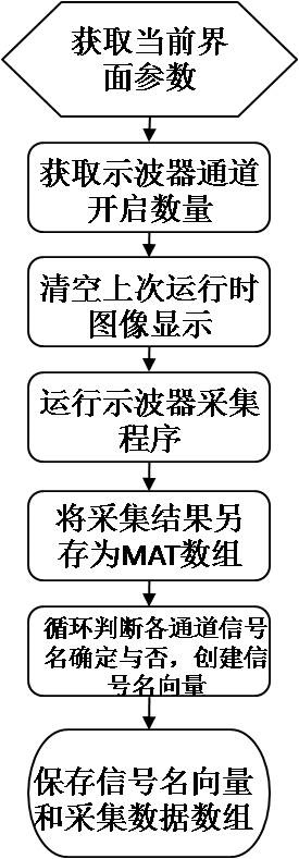
[0073] Such as figure 1 As shown, the GUI interface program first obtains the parameter values ​​filled in by the current GUI interface user; calculates the nu...


PUM


Abstract

The invention relates to a method for continuous data acquisition and display of an engine. Using the characteristics that a digital oscilloscope can communicate with MATLAB and export the collected data, a method for connecting MATLAB and an oscilloscope and controlling the oscilloscope for acquisition, transmission and real-time monitoring is developed. Through the development of the GUI user interface, the platform can obtain the signal name and acquisition mode filled in and selected by the user. Through MATLAB, the digital oscilloscope can be connected, set, collected, stored, and disconnected, and then rely on the background program to display the collected signal in real time. After the end, the collected data and signal names are automatically saved, and the functions of quantitative collection, real-time display and automatic saving of signal names are realized.

Description

technical field [0001] The invention belongs to the field of engine testing, and in particular relates to a method for collecting and displaying continuous data of an engine. Background technique [0002] Signal acquisition has increasingly become an important task in the research and development of electronically controlled engine control systems. Digital oscilloscopes are increasingly favored by engine testers for their advantages of portability, ease of use, and accurate measurement. [0003] In order to analyze each signal, tests such as engine durability require long-term high-speed acquisition. In the electronically controlled engine test, there are generally a large number of acquisition channels, and the signal names corresponding to each channel are easy to confuse when saving data; and the general transmission mode of the oscilloscope is that the oscilloscope first stores the acquisition data in its own buffer area, and transmits the data after the acquisition is c...

Claims


Application Information

Patent Timeline
Patent Type & Authority Patents(China)
IPC IPC(8): G01M15/00G06F30/20
CPCG01M15/00
Inventor 刘松郭延超段松松章明胡友耀
Owner LUOYANG TRACTORS RES INST
Why Eureka
Try Eureka