Novel leakage current measuring device and method

A technology of measuring device and leakage current, applied in the direction of measuring device, measuring only current, measuring electrical variables, etc., can solve the problems of unbearable lines, large spacing, large current transformers, etc.

Pending Publication Date: 2020-06-26
金一凡
View PDF4 Cites 1 Cited by
  • Summary
  • Abstract
  • Description
  • Claims
  • Application Information

AI Technical Summary

Problems solved by technology

This method has certain difficulties in the actual operation process, that is, the distance between the phases of the 400V overhead line is very large, and it is di

Method used


Image

  • Novel leakage current measuring device and method
  • Novel leakage current measuring device and method
  • Novel leakage current measuring device and method

Examples


Embodiment 1

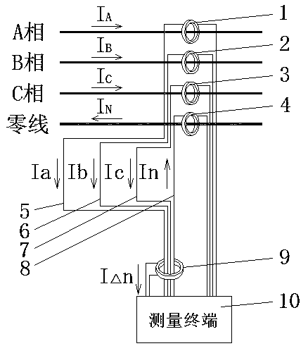
[0036] Depend on figure 1 , A-phase line current IA passes through A-phase current transformer 1 to generate induced current Ia; B-phase line current IB passes through B-phase current transformer 2 to generate induced current Ib; C-phase line current IC passes through C-phase current Transformer 3 generates induced current Ic; neutral current IN passes through neutral current transformer 4 to generate induced current In. The secondary wire 5 of phase A current transformer, the secondary wire 6 of phase B current transformer, the secondary wire 7 of phase C current transformer, and the secondary wire 8 of neutral current transformer pass through the hole of measuring current transformer 9 , the measuring current transformer 9 generates an induced current IΔn and passes it into the measuring terminal 10, and the measuring terminal 10 can calculate the leakage current on the original line.

[0037]When the secondary wire 5 of phase A current transformer, the secondary wire 6 of ...

Embodiment 2

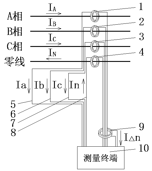
[0039] Depend on figure 2 , when the measuring current transformer 9 is installed at the current output end of the measuring terminal 10, as long as the four wires are connected in the same direction, the measuring method is the same as that of the first embodiment.

Embodiment 3

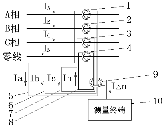
[0041] Depend on image 3 , when the secondary side of A-phase current transformer 1, B-phase current transformer 2, C-phase current transformer 3, and zero-line current transformer 4 is not connected to the measurement terminal 10, as long as the four wires are connected in the same direction, the measurement The method is the same as in Example 1.

[0042] The method provided by the present invention is not only applicable to low-voltage 400V three-phase lines, but also suitable for low-voltage 400V single-phase lines, by Figure 4 , only need to install a total of four current transformers on the A phase, B phase, C phase and the neutral line to install a total of two current transformers on the live line and the neutral line, and the other remains unchanged. Because A-phase current transformer 1, B-phase current transformer 2, C-phase current transformer 3, and zero-line current transformer 4 are current transformers of the same specification, so take A-phase current tran...


PUM


Abstract

The invention provides a novel leakage current measuring device and a method thereof. The device is characterized in that the device comprises an A-phase current transformer, a B-phase current transformer, a C-phase current transformer, a zero line current transformer, an A-phase current transformer secondary line, a B-phase current transformer secondary line, a C-phase current transformer secondary line, a zero line current transformer secondary line, a measurement current transformer and a measurement terminal; the A-phase current transformer, the B-phase current transformer, the C-phase current transformer and the zero line current transformer are respectively installed on an A phase, a B phase, a C phase and a zero line of a line to be measured; the A-phase current transformer secondary line, the B-phase current transformer secondary line, the C-phase current transformer secondary line and the zero line current transformer secondary line penetrate through holes of the measurement current transformer. According to the invention, the leakage current of the original line is calculated by measuring the induced current of the current transformer, so the problem that a transformer isdifficult to sleeve to measure the leakage current due to overlarge line distance of the low-voltage 400V overhead line is solved.

Description

technical field [0001] The invention relates to the problem of leakage current measurement of low-voltage 400V overhead lines, in particular to a novel leakage current measurement device and method thereof. Background technique [0002] The way to measure the leakage current of the existing low-voltage 400V line is: if it is a three-phase line, use a current transformer to cover the four wires of phase A, phase B, phase C and the neutral line together. It is the size of the leakage current; if it is a single-phase line, also use a current transformer to put the live wire and the neutral wire together, and the measured current size is the size of the leakage current. This method has certain difficulties in the actual operation process, that is, the distance between the phases of the 400V overhead line is very large, and it is difficult to put them together. If you want to use a current transformer on it, the current transformer needs to be very large and heavy. , the line ca...

Claims


Application Information

Patent Timeline
IPC IPC(8): G01R31/52G01R19/00
CPCG01R19/0092
Inventor 金一凡
Owner 金一凡
Why Eureka
Try Eureka