Screen frame and laser projection display device

A frame and screen technology, applied in projection devices, optics, instruments, etc., can solve problems such as poor user experience, low installation efficiency of frame screens, unfavorable self-installation, etc., to save assembly costs, improve product experience, and high installation efficiency Effect

Active Publication Date: 2020-06-26
QINGDAO HISENSE LASER DISPLAY CO LTD
View PDF5 Cites 0 Cited by
  • Summary
  • Abstract
  • Description
  • Claims
  • Application Information

AI Technical Summary

Problems solved by technology

[0004] However, on the one hand, when aligning the side frame 20 or the through-hole connection holes provided on the extension part 201, it often takes multiple attempts to achieve accurate alignment, and after alignment, the relative position must be kept unchanged. For example, keep the state where the connector extends into the chute at this time until the fixing of the fastener is completed. On the other hand, usually in order to make the corner connector 20 and the side frame 10 assembled more firmly, it is necessary to set multiple pairs of connecting holes. Therefore, the above-mentioned installation process needs to be repeated many times, which makes the installation efficiency of the frame-type screen very low. Usually, the installation of one above-mentioned screen frame requires two people to cooperate for about 100 minutes. Self-installation

Method used


Image

  • Screen frame and laser projection display device
  • Screen frame and laser projection display device
  • Screen frame and laser projection display device

Examples


Embodiment 1

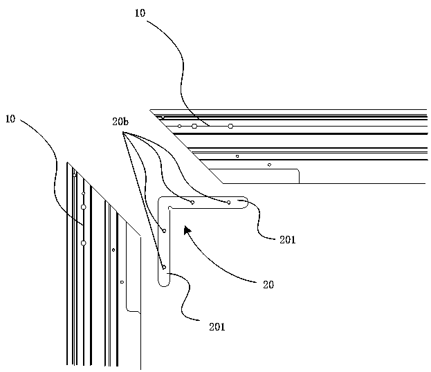
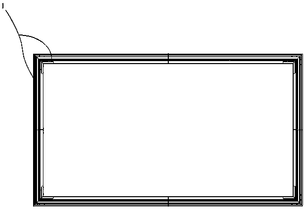
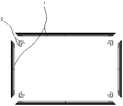
[0025] Figure 2a It is a structural schematic diagram of the screen frame assembly provided by Embodiment 1 of the present invention. Figure 2b It is an exploded schematic diagram of the screen frame provided by Embodiment 1 of the present invention. Figure 3a It is a schematic diagram of the connection positions of two adjacent side frames in the screen frame provided by Embodiment 1 of the present invention. Figure 3b It is an exploded schematic diagram of the connection positions of two adjacent side frames in the screen frame provided by Embodiment 1 of the present invention. Figure 4a , Figure 4b It is a schematic diagram of the connection structure of the connecting piece and the side frame in the screen frame provided by Embodiment 1 of the present invention. Figure 5a , Figure 5b It is a structural schematic diagram of the first connecting member in the screen frame provided by Embodiment 1 of the present invention. Figure 6a , Figure 6b It is a schemat...

Embodiment 2

[0073] Embodiment 2 of the present invention also provides a laser projection display device. Figure 8 It is a schematic structural diagram of a laser projection display device provided in Embodiment 2 of the present invention. like Figure 8As shown, the laser projection display device 300 of this embodiment includes a projection screen 301 and the screen frame 302 described in the above embodiment, and the screen frame 302 is surrounded by the outside of the projection screen 301 . In addition, the laser projection display device 300 also includes a projection host 303 and the like. Wherein, the specific structure, function and working principle of the screen frame 302 have been described in detail in the foregoing embodiments, and will not be repeated here.

[0074] Specifically, the projection screen 301 in the laser projection display device 300 is usually a soft or hard optical film, so that the projection screen 301 can be used to display the image picture projected ...


PUM


Abstract

The invention provides a screen frame and a laser projection display device. The screen frame comprises a plurality of side frames connected end to end, and a plurality of connecting parts are arranged at the joint of every two adjacent side frames. Containing grooves corresponding to the connecting parts in a one-to-one mode are formed in the joints of the side frames and the adjacent side frames, the connecting parts are provided with inserting parts capable of extending into the containing grooves, the inserting parts are provided with telescopic clamping parts, and containing holes corresponding to the clamping parts are formed in the groove walls of the containing grooves. The clamping parts are used for extending into the containing holes to realize positioning; moreover, the inserting parts are connected with the side wall of the containing grooves through a fastener, so that the relative positions of the connecting parts and the side frame can be quickly positioned, and the mounting efficiency is improved.

Description

technical field [0001] The invention relates to the field of displays, in particular to a screen frame and a laser projection display device. Background technique [0002] With the continuous development of science and technology and the improvement of people's living standards, new laser projection display devices have been more and more widely used. [0003] At present, among the laser projection screens, the frame-type screen has the advantages of light weight, low cost, and easy assembly, and thus has been widely used. Among them, the frame-type screen is formed by splicing multiple side frames. figure 1 It is a structural schematic diagram of a framed screen in the prior art. like figure 1 As shown, specifically, when the side frames 10 are spliced ​​and connected, the two side frames 10 corresponding to the adjacent two sides of the screen are connected through the corner connectors 20 . Specifically, the corner connector 20 has two protruding parts 201 at right an...

Claims


Application Information

Patent Timeline
Patent Type & Authority Applications(China)
IPC IPC(8): G03B21/56
CPCG03B21/56
Inventor 陈波黄永达赵飞
Owner QINGDAO HISENSE LASER DISPLAY CO LTD
Why Eureka
Try Eureka