Dehumidification power distribution cabinet

A technology for power distribution cabinets and boxes, which is applied in substation/power distribution device shells, electrical components, humidity control, etc., can solve problems such as damage, increased humidity, and difficulty in reducing the service life of components, so as to achieve service life guarantee and avoid Sustained damage, reduced maintenance and replacement costs

Inactive Publication Date: 2020-06-26
FUJIAN DATANG INT NINGDE POWER GENERATION
View PDF10 Cites 2 Cited by
  • Summary
  • Abstract
  • Description
  • Claims
  • Application Information

AI Technical Summary

Problems solved by technology

[0004] The purpose of the present invention is to solve the problem in the prior art that it is difficult to reduce the damage to the service life of components after the internal humidity of the power distribution cabinet increases, and proposes a dehumidification power distribution cabinet

Method used


Image

  • Dehumidification power distribution cabinet
  • Dehumidification power distribution cabinet

Examples


Embodiment

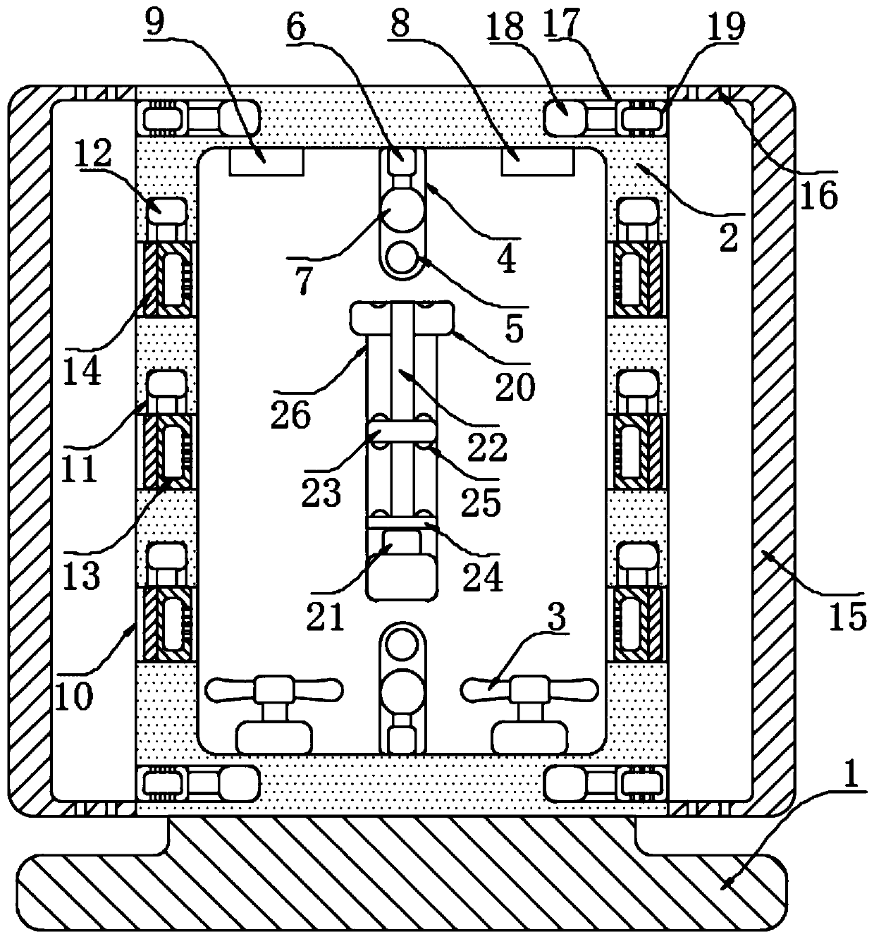
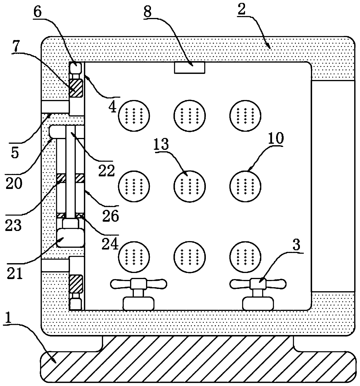
[0018] refer to Figure 1-2 , a dehumidification power distribution cabinet, including a base 1 and a box body 2 installed on the upper end of the base 1, a plurality of fans 3 are fixed on the inner bottom of the box body 2, and two ventilation slots 4 are symmetrically opened on the side wall of the box body 2, The inner walls of the two ventilation slots 4 are provided with ventilation holes 5, and the inner walls of the two ventilation slots 4 away from the corresponding ventilation holes 5 are fixed with opening and closing push rods 6, and the extension ends of the two opening and closing push rods 6 are fixed. There is a closed plate 7, a humidity sensor 8 and a temperature sensor 9 are fixed on the inner top of the box body 2, and a plurality of dehumidification tanks 10 are opened through the two symmetrical side walls of the box body 2, and each dehumidification tank 10 is equipped with a dehumidification structure inside , the inner wall of casing 2 is provided with...


PUM


Abstract

The invention discloses a dehumidification power distribution cabinet. The cabinet comprises a base and a box body mounted at the upper end of the base, a plurality of fans are fixed at the inner bottom of the box body; two ventilation grooves are symmetrically formed in the side wall of the box body; ventilation holes are formed in the inner walls of the two ventilation grooves in a penetrating mode, opening and closing push rods are fixed to the inner walls of the ends, away from the corresponding ventilation holes, of the two ventilation grooves, sealing plates are fixed to the extending ends of the two opening and closing push rods, and a humidity sensor and a temperature sensor are fixed to the inner top of the box body. The method has the advantages that the method is simple; the timing motor drives the screw rod to rotate; therefore, the sliding block moves upwards; the timing purpose is achieved; and if the internal humidity of the box body is controlled in the time period whenthe sliding block moves upwards to the top, it shows that the external humidity is not increased continuously, the internal operation of the box body is normally carried out, and if the humidity is not quickly controlled, the sealing plate seals the ventilation hole, so that external humid air is prevented from entering the box body, and the internal humidity of the box body is not increased anymore.

Description

technical field [0001] The invention relates to the technical field of power distribution cabinets, in particular to a dehumidification power distribution cabinet. Background technique [0002] Power distribution cabinets are divided into power distribution cabinets, lighting distribution cabinets, and metering cabinets. They are the final equipment of the power distribution system; power distribution cabinets are collectively referred to as motor control centers. ; The motor control center is used in occasions where the load is concentrated and there are many circuits; they distribute the electric energy of a certain circuit of the upper-level power distribution equipment to the nearest load. This level of equipment shall provide protection, monitoring and control of the load. [0003] When the power distribution cabinet is used outdoors, it will be greatly affected by the external environment, especially the influence of temperature and humidity, which will lead to a redu...

Claims


Application Information

Patent Timeline
Patent Type & Authority Applications(China)
IPC IPC(8): H02B1/56H02B1/28G05D22/02
CPCH02B1/565H02B1/28G05D22/02
Inventor 杨海卫
Owner FUJIAN DATANG INT NINGDE POWER GENERATION
Why Eureka
Try Eureka