An ultra-high-speed placement method and placement head

An ultra-high-speed, placement head technology, applied in the direction of electrical components, electrical components, etc., can solve the problems of low efficiency, low cost performance, high production cost of placement machines, etc., to achieve simple steps, improve accuracy, and increase placement speed Effect

Active Publication Date: 2021-06-11
方强
View PDF11 Cites 0 Cited by
  • Summary
  • Abstract
  • Description
  • Claims
  • Application Information

AI Technical Summary

Problems solved by technology

[0003] In order to break through the speed bottleneck of the placement machine, the current main placement method has cumbersome steps and low efficiency, which makes the production cost of the placement machine more and more high, and the cost performance is not high.

Method used


Image

  • An ultra-high-speed placement method and placement head
  • An ultra-high-speed placement method and placement head
  • An ultra-high-speed placement method and placement head

Examples


specific Embodiment approach

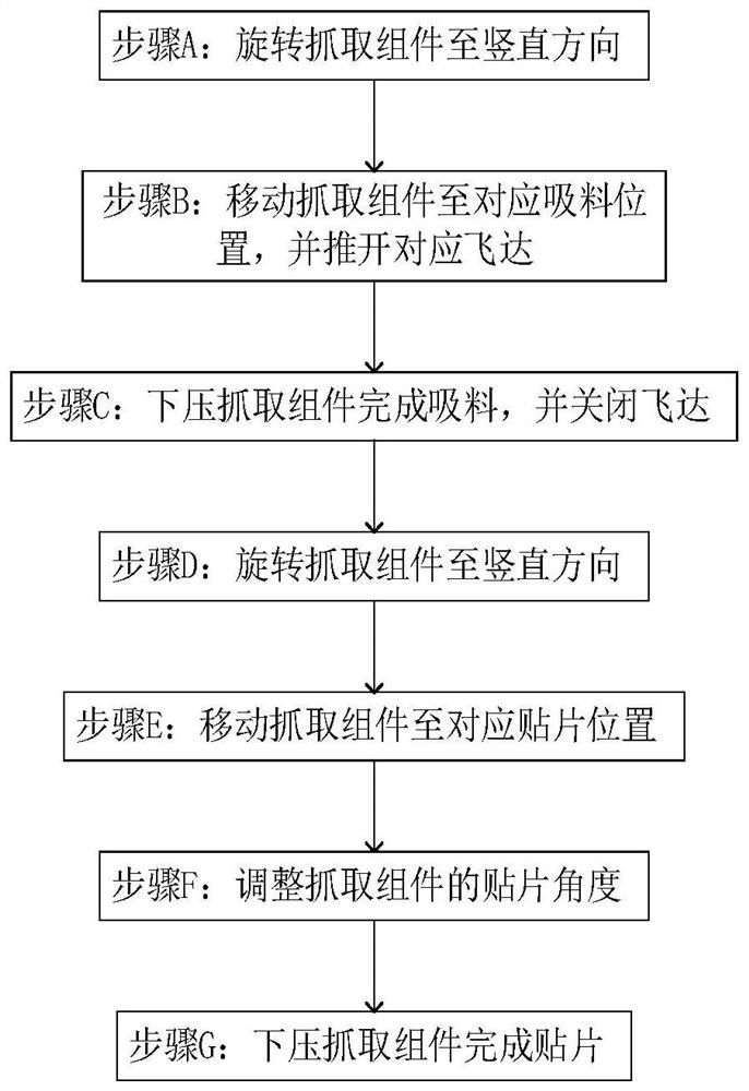
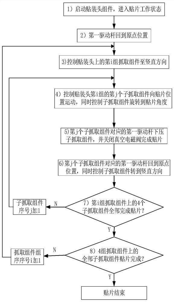
[0111] For the above method, for ease of understanding, steps A to C of the placement method can be collectively referred to as the suction method, and steps D to G can be collectively referred to as the placement method, and as an example, it is assumed that 4 sets of grabbing components are set (A row of sub-grabbing assemblies arranged in the same direction along the direction of the shaft center line of the horizontal turret assembly is a group), each group of grabbing assemblies has 4 sub-grabbing assemblies, that is, n=4, m =4. Each sub-grabbing assembly has a suction nozzle for picking up components, so there are 16 sub-grabbing assemblies and suction nozzles in total. Taking this as an example, the specific implementation of the ultra-high-speed patch method of the present application is as follows:

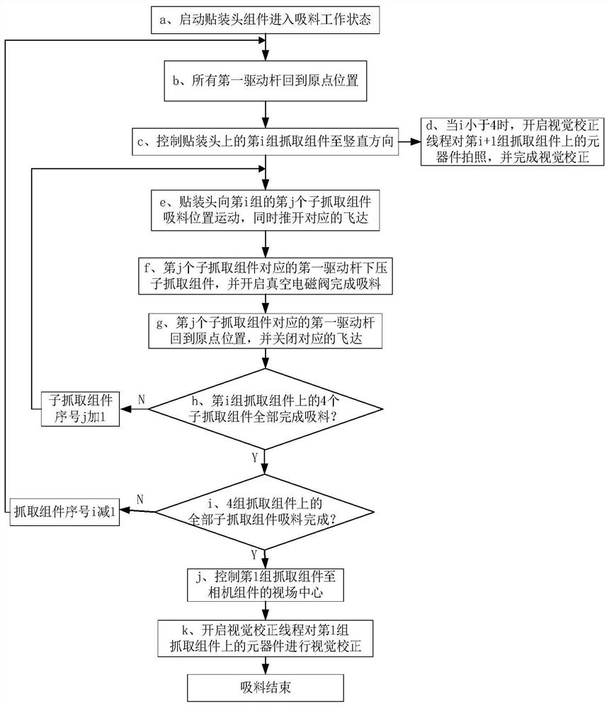
[0112] Such as figure 2 As shown, the steps A to C collectively referred to as the suction method are complete and detailed as follows:

[0113] a. Start the placement...


PUM


Abstract

The application discloses an ultra-high-speed placement method and a placement head. The placement head includes a grabbing assembly. The placement method includes: step A: rotating the grabbing assembly to a vertical direction; step B: moving the grabbing assembly Take the component to the corresponding suction position, and push the corresponding feeder; Step C: Press down on the grabbing component to complete the suction, and close the feeder; Step D: Rotate the grabbing component to the vertical direction; Step E: Move the grabbing Components to the corresponding placement position; Step F: Adjust the placement angle of the grabbing component; Step G: Press down on the grabbing component to complete the placement. The placement method of the present application has simple steps, can adjust the placement angle of the grasping component, improves the accuracy of placement, and greatly improves the placement speed of equipment such as placement machines.

Description

technical field [0001] The application relates to the field of automation equipment, in particular to an ultra-high-speed placement method and a placement head. Background technique [0002] The placement machine plays a very important role in the manufacturing process of circuit board packaging. It is the largest investment and the most advanced technology in the production equipment of contemporary mainstream electronic assembly technology. It has the greatest impact on the production capacity and production efficiency of the SMT (Surface Mounted Technology) production line. device of. In fact, the most faults and speed bottlenecks largely come from the placement process, so the development of placement machine equipment is the most eye-catching. [0003] In order to break through the speed bottleneck of the placement machine, the current main placement method has cumbersome steps and low efficiency, which makes the production cost of the placement machine higher and high...

Claims


Application Information

Patent Timeline
Patent Type & Authority Patents(China)
IPC IPC(8): H05K13/04
CPCH05K13/0404H05K13/0406
Inventor 方强
Owner 方强
Why Eureka
Try Eureka