Fuel filler neck provided with an attachment device

A technology for fastening devices and fuel filling, which is applied to power devices, arrangements combined with internal combustion engine fuel supply, hoses, etc., and can solve problems such as being unable to maintain positions independently

Pending Publication Date: 2020-06-26
PEZHO SITROEN AUTOMOBILS SA
View PDF15 Cites 0 Cited by
  • Summary
  • Abstract
  • Description
  • Claims
  • Application Information

AI Technical Summary

Problems solved by technology

This leads to the need to fasten the tube to the wheel arch, especially if the tube includes a flexible sleeve for connection to the fuel tank, whi

Method used


Image

  • Fuel filler neck provided with an attachment device
  • Fuel filler neck provided with an attachment device
  • Fuel filler neck provided with an attachment device

Examples


Embodiment Construction

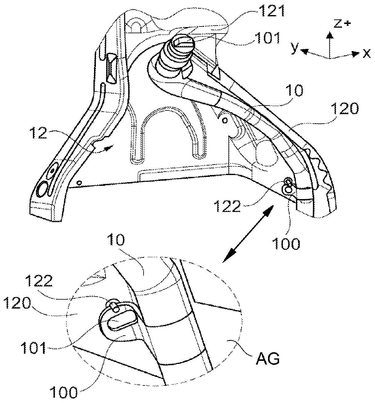
[0021] refer to Figure 2 to Figure 4 as well as Figure 5A , Figure 5B , a specific embodiment 20 of the fuel filler pipe according to the invention, and its fastening in the wheel arch 12 will now be described.

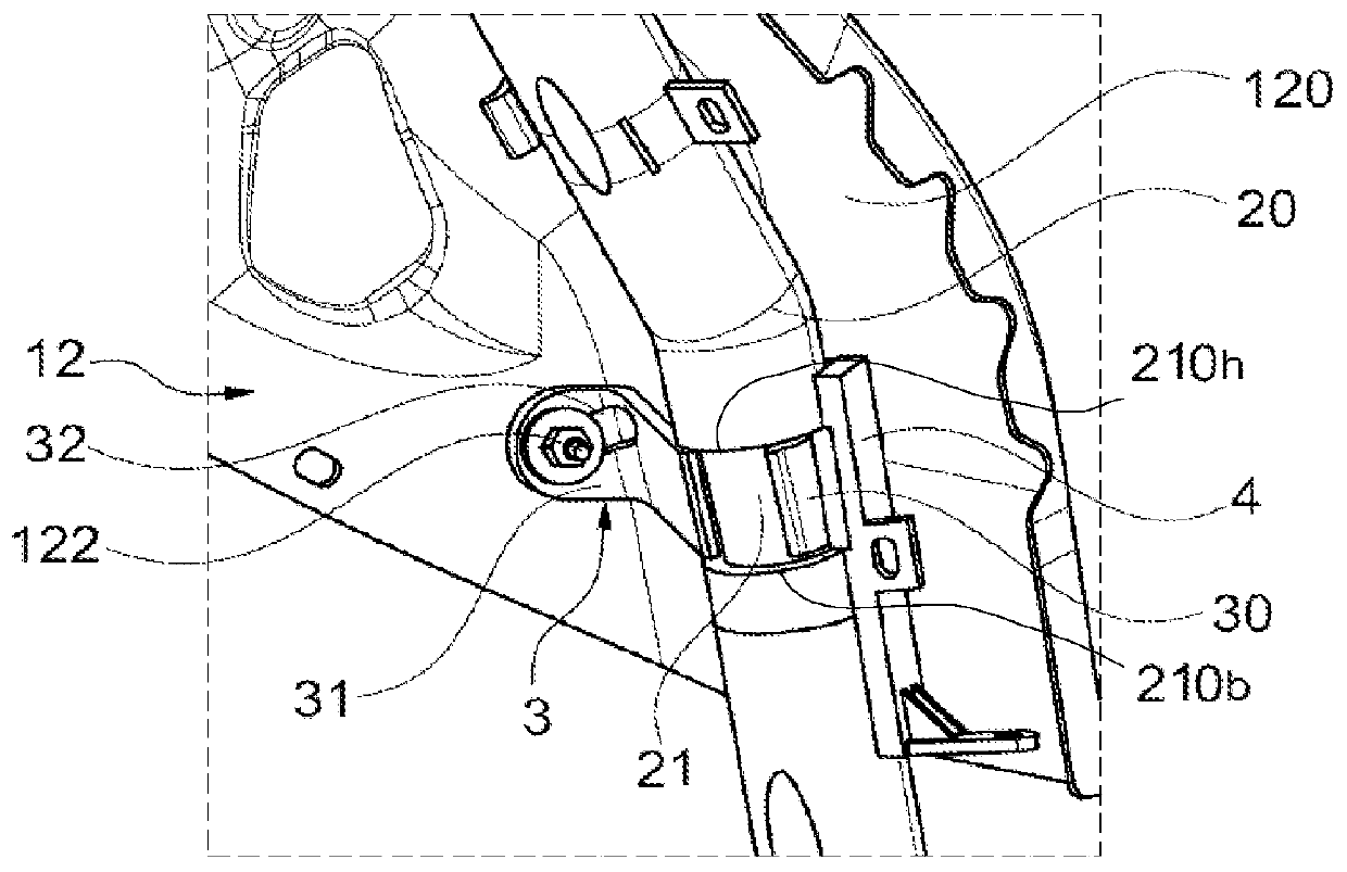
[0022] The fuel filler pipe 20 is usually a part made of plastic and comprises a pivotable fastening claw 3 . The pivotable fastening pawl 3 is mounted in a rigid or semi-rigid part of the tube 20 . More specifically, in this particular example, as figure 2 As shown, the fastening pawl 3 is pivotally mounted on a portion 21 of the tube 20 forming a rotational support. The rotational support part 21 is a cylindrical part, which here has an outer diameter which is smaller than the outer diameter of the tube. The swivel support portion 21 is delimited in height by two opposing annular shoulders 210h, 210b to prevent translation of the pivotable fastening pawl 3 .

[0023] Such as image 3 As shown, the pivotable fastening claw 3 mainly includes a ring member 3...


PUM


Abstract

The fuel filler neck (20) comprises an attachment device arranged in such a way as to allow the neck to be attached in a wheel arch (12) of a vehicle. According to the invention, the attachment devicecomprises a pivoting attachment bracket (3), the pivoting attachment bracket comprising a ring forming a hinge (30) that is mounted so as to be able to rotate with friction on a portion forming a rotation support (21 ) that is comprised in the neck.

Description

technical field [0001] The present invention generally relates to the field of motor vehicles. More specifically, the invention relates to a fuel filler pipe equipped with fastening means for fastening the pipe in a wheel arch of a vehicle. Background technique [0002] In motor vehicles, fuel filler pipes are typically located in the wheel wells of the vehicle. The tube connects the fuel tank cap to the fuel tank located under the floor of the vehicle. The course of the tube in the wheel arch is restricted by current regulations in order to reduce the consequences in the event of a collision. This leads to the need to fasten the tube to the wheel arch, especially if the tube includes a flexible sleeve for connection to the fuel tank, which makes it impossible for the tube to remain in place autonomously, especially in the wheel arch The lower part of the can't keep itself in place. [0003] exist figure 1 In a known configuration of the present invention, the fuel fill...

Claims


Application Information

Patent Timeline
IPC IPC(8): B60K15/01F16L3/01F16L3/13
CPCB60K15/01F16L3/13
Inventor 特里斯坦·乌莱特弗兰克·布里奥让·弗朗索瓦·莫伊特隆其他发明人请求不公开姓名
Owner PEZHO SITROEN AUTOMOBILS SA
Why Eureka
Try Eureka