L-shaped plate punching die

A plate, L-shaped technology, applied in the field of stamping, can solve the problem of inability to achieve simultaneous processing on both sides, and achieve the effect of improving the efficiency of punching

Inactive Publication Date: 2020-06-30
郑冬青
View PDF1 Cites 2 Cited by
  • Summary
  • Abstract
  • Description
  • Claims
  • Application Information

AI Technical Summary

Problems solved by technology

However, the above-mentioned L-shaped steel member punching device can only punch one side of the L-shaped steel member at a time, and cannot achieve the purpose of synchronous processing of both sides.

Method used


Image

  • L-shaped plate punching die

Examples


Embodiment Construction

[0014] The present invention will be further described in detail below in conjunction with the accompanying drawings and embodiments.

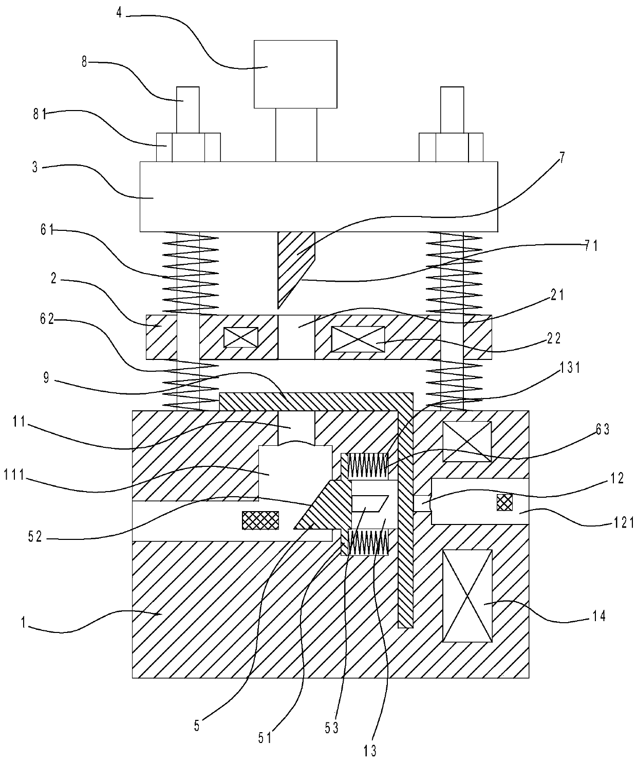
[0015] Such as figure 1 As shown, the L-shaped plate punching die in the implementation of the present invention includes a bottom die 1, a top die 2, a movable template 3, a power mechanism, a connecting spring 61, a balance spring 62, a stamping block 5, a side spring 63, and an adsorption electromagnet 14 and discharge electromagnet 22.

[0016] Wherein, a guide column 8 is erected on the bottom mold 1, and a limit groove for accommodating one side of the L-shaped plate 9 is provided on the bottom mold 1, and an upper punch 11 is provided on the upper side wall of the bottom mold 1, and the upper punch The bottom of 11 communicates with a first enlarging channel 111 with an enlarged caliber, that is, the caliber of the first enlarging channel 111 is greater than that of the upper punching port 11, which is convenient for the discharge of w...


PUM


Abstract

The invention discloses an L-shaped plate punching die. The L-shaped plate punching die comprises a bottom die body, a top die body and a movable die plate. Guide pillars are vertically arranged on the bottom die body. The L-shaped plate punching die is characterized in that a limiting groove is formed in the bottom die body, an upper punching opening, a first expanding channel communicating withthe upper punching opening and a sliding block channel communicating with the first expanding channel are formed in the bottom die body, a punching block is arranged in the sliding block channel in asliding mode, an inclined face is formed on one side of the punching block, a side punching head is arranged on the other side of the punching block, an upper punching head is connected to the lower portion of the movable die plate, a pushing face is arranged at the end of the upper punching head, a power mechanism for pushing the movable die plate to move along the guide pillars is arranged on the movable die plate, an upper through hole for the upper punching head to penetrate through is formed in the top die body, connecting springs are arranged on the guide pillars in a sleeving mode, theupper ends of the connecting springs are connected with the movable die plate, and the lower ends of the connecting springs are connected with the top die body. The L-shaped plate punching die is usedfor synchronously punching the two side faces of an L-shaped thin plate, positioning and installing of the L-shaped plate can be facilitated, and the punching efficiency is high.

Description

technical field [0001] The invention relates to the stamping field, in particular to an L-shaped plate punching die. Background technique [0002] For the particularity of the shape of the L-shaped sheet, it is necessary to design a special included angle for clamping. Manual punching is used. Each punching can only punch one side. When the other side also needs to be punched, it needs to be punched. The L-shaped plate is repositioned and clamped, and the processing efficiency is low. At the same time, it is also prone to overturning during punching, which is likely to cause danger. [0003] For the particularity of L-shaped plate processing, the existing Chinese invention patent with publication number CN110355262A discloses "A Punching Device for L-shaped Steel Members for Electric Control Cabinets", which includes a processing table and multiple supporting feet installed at the lower end of the processing table. And the frame set on the upper end of the processing table,...

Claims


Application Information

Patent Timeline
IPC IPC(8): B21D28/34B21D28/24
CPCB21D28/243B21D28/34
Inventor 郑冬青
Owner 郑冬青
Why Eureka
Try Eureka