Chemical industry pressure vessel tank body fabrication method

A technology for pressure vessels and manufacturing methods, applied in the direction of manufacturing tools, casting molding equipment, metal processing equipment, etc., can solve the problems of reducing the production efficiency of chemical pressure vessels, cumbersome welding and testing processes, and low concentricity accuracy of chemical pressure vessels , to achieve the effect of improving manufacturing precision, avoiding separation, and accurate concentricity

Active Publication Date: 2020-06-30
江苏格安德环保工程科技有限公司
View PDF8 Cites 4 Cited by
  • Summary
  • Abstract
  • Description
  • Claims
  • Application Information

AI Technical Summary

Problems solved by technology

[0004] (1) When chemical pressure vessels are manufactured by manual production, the chemical pressure vessels are usually fixed and spliced ​​manually first, and then the fixed and spliced ​​chemical pressure vessels are welded. After the welding is completed, the concentricity is tested. The single splicing, welding and testing process of pressure vessels is cumbersome, which reduces the production efficiency of chemical pressure vessels;
[0005] (2) When the existing chemical pressure vessel manufacturing equipment manufactures chemical pressure vessels, the existing chemical pressure vessel manufacturing equipment usually fixes and splices the chemical pressure vessels first, and then directly welds the fixed and spliced ​​chemical pressure vessels, and the welding is completed Then inspect it. The process of inspection after welding will easily lead to low concentricity accuracy of the finished chemical pressure vessel, which needs to be repaired, thereby reducing the production efficiency of chemical pressure vessels.

Method used


Image

  • Chemical industry pressure vessel tank body fabrication method
  • Chemical industry pressure vessel tank body fabrication method
  • Chemical industry pressure vessel tank body fabrication method

Examples


Embodiment Construction

[0041] In order to make the technical means realized by the present invention, creative features, goals and effects easy to understand, the following combination Figure 1 to Figure 10 , to further elaborate the present invention.

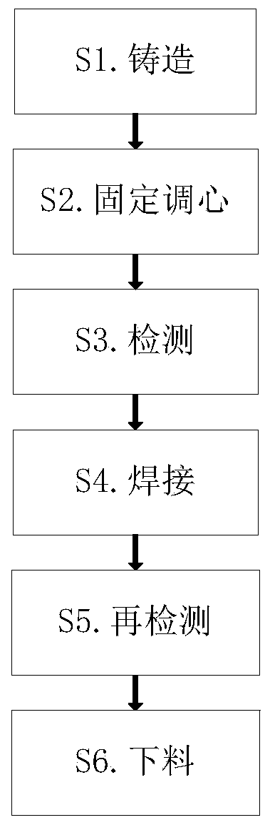
[0042] A method for manufacturing a tank body of a chemical pressure vessel, the specific manufacturing method is as follows:

[0043] S1. Casting: Manually cast molten iron into the shape of a pressure vessel;

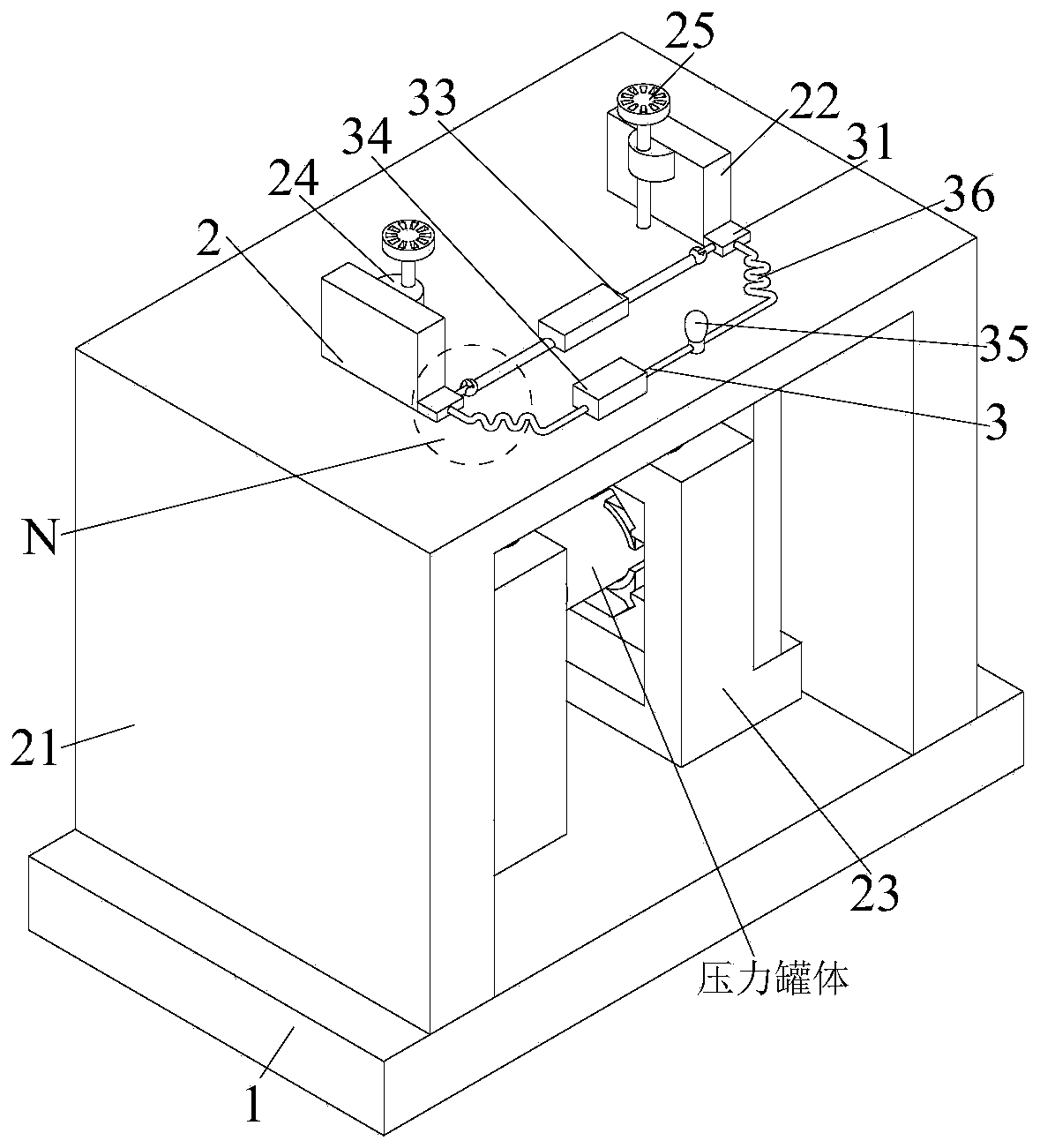
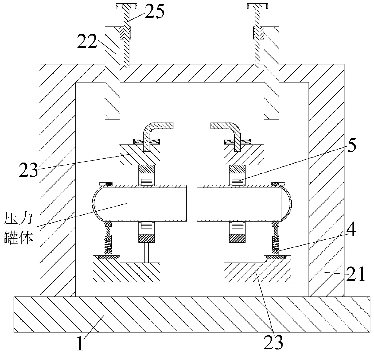
[0044] S2. Fixed centering: After the casting is completed, the left and right pressure vessel tanks are locked and fixed in the position adjustment device (2) by the locking mechanism (46). After the pressure vessel tank is fixed, manually rotate the position adjustment device (2) and centering device (5), thereby carrying out centering to pressure vessel tank body;

[0045] S3. Detection: detect whether the centers of the left and right pressure vessel tanks are on the same straight line by turning on and off the indicator light (35); ...


PUM


Abstract

The invention relates to a chemical industry pressure vessel tank body fabrication method. Equipment used in the chemical industry pressure vessel tank body fabrication method comprises an installation plate, position adjusting devices, a detection device, two locking devices and two center adjusting devices, wherein the upper end of the installation plate is provided with the position adjusting devices, the upper ends of the position adjusting devices are provided with monitoring devices, the lower ends of the position adjusting devices are provided with the locking devices in a bilateral symmetry manner, and the inner sides of the locking devices are provided with the center adjusting devices. By means of the chemical industry pressure vessel tank body fabrication method provided by theinvention, the problems that when a chemical industry pressure vessel is fabricated manually, the chemical industry pressure vessel is firstly fixed and spliced and then is welded, then concentricitydetection is performed after welding is finished, and the chemical industry pressure vessel single-time fabrication process is tedious; when existing chemical industry pressure vessel fabrication equipment performs fabrication, the chemical industry pressure vessel is firstly fixed and welded and then is detected after the welding is finished, the process of detecting after the welding is prone tocausing the concentricity of the fabricated chemical industry pressure vessel to be inaccurate, and repairing needs to be performed on the fabricated chemical industry pressure vessel again; and thelike can be solved.

Description

technical field [0001] The invention relates to the technical field of chemical container manufacturing, in particular to a method for manufacturing a chemical pressure vessel body. Background technique [0002] A pressure vessel is a closed container that can withstand pressure. The pressure vessel has a wide range of uses, and it has an important position and role in many sectors such as industry, civil, military, and many fields of scientific research. Among them, it is most used in chemical industry and petrochemical industry. In the field of chemical industry and petrochemical industry, pressure vessels are mainly used for heat transfer, mass transfer, reaction and other processes, as well as storage and transportation of pressurized gas or liquefied gas; they are also widely used in other industrial and civil fields, such as air compressor. All kinds of special compressors and auxiliary machines of refrigeration compressors (coolers, buffers, oil-water separators, g...

Claims


Application Information

Patent Timeline
Patent Type & Authority Applications(China)
IPC IPC(8): B23K37/053B23P15/00B22C9/24
CPCB22C9/24B23K37/053B23P15/00
Inventor 何卫统
Owner 江苏格安德环保工程科技有限公司
Why Eureka
Try Eureka