Rotary type welding device

A welding device and rotary technology, which is applied in the direction of auxiliary devices, welding equipment, auxiliary welding equipment, etc., can solve the problem of unstable placement of workpieces

Inactive Publication Date: 2018-06-05
新昌县丽晶工业产品设计有限公司
View PDF0 Cites 0 Cited by
  • Summary
  • Abstract
  • Description
  • Claims
  • Application Information

AI Technical Summary

Problems solved by technology

[0002] The existing rotary welding table can generally rotate around the rotating shaft, but generally there is only one rotating shaft connected to the bottom of the welding table, which makes the workpiece placed on the welding table unstable, so it is necessary to improve

Method used


Image

  • Rotary type welding device
  • Rotary type welding device
  • Rotary type welding device

Examples


Embodiment Construction

[0020] The following are specific embodiments of the present invention and in conjunction with the accompanying drawings, the technical solutions of the present invention are further described, but the present invention is not limited to these embodiments.

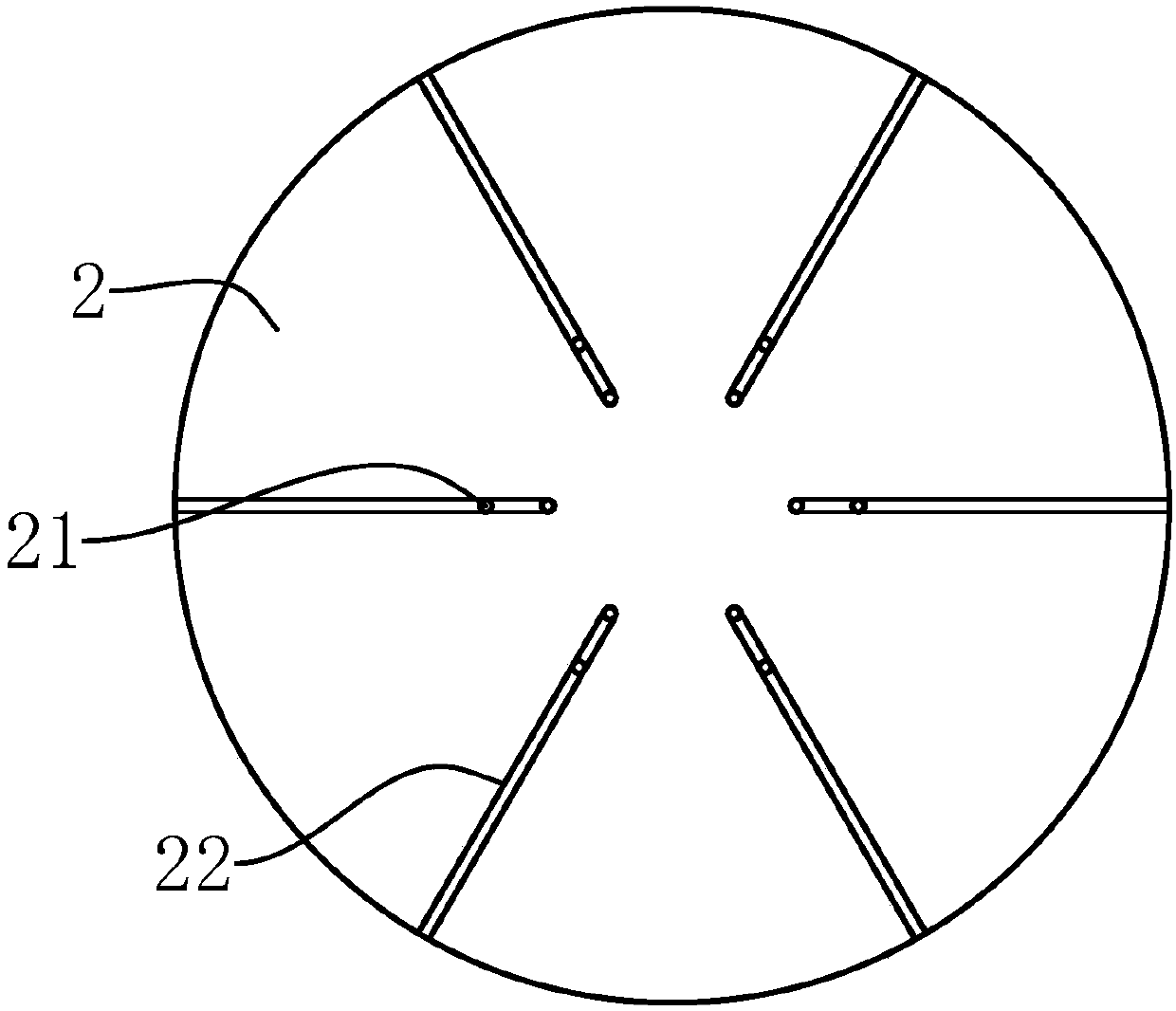
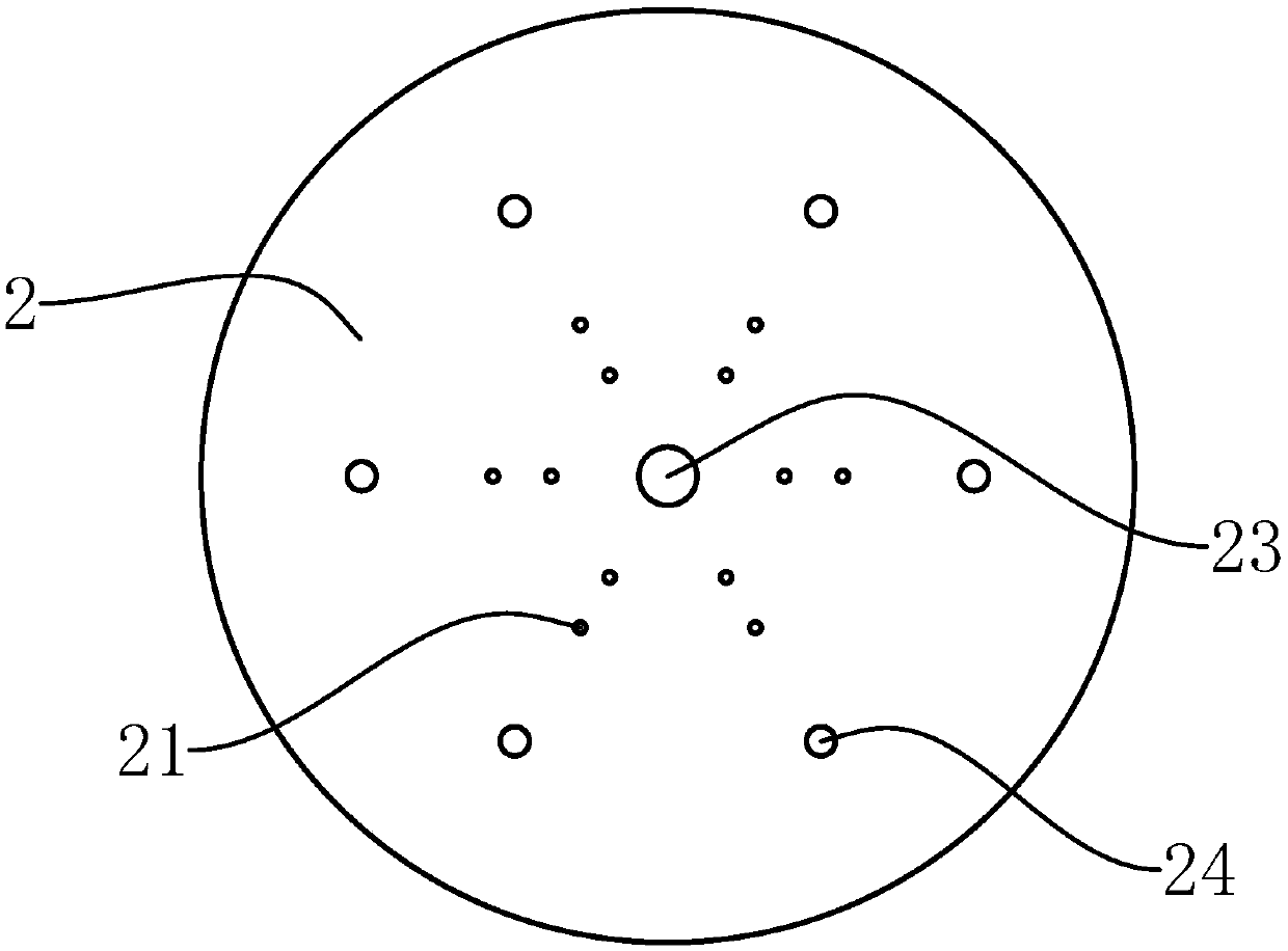
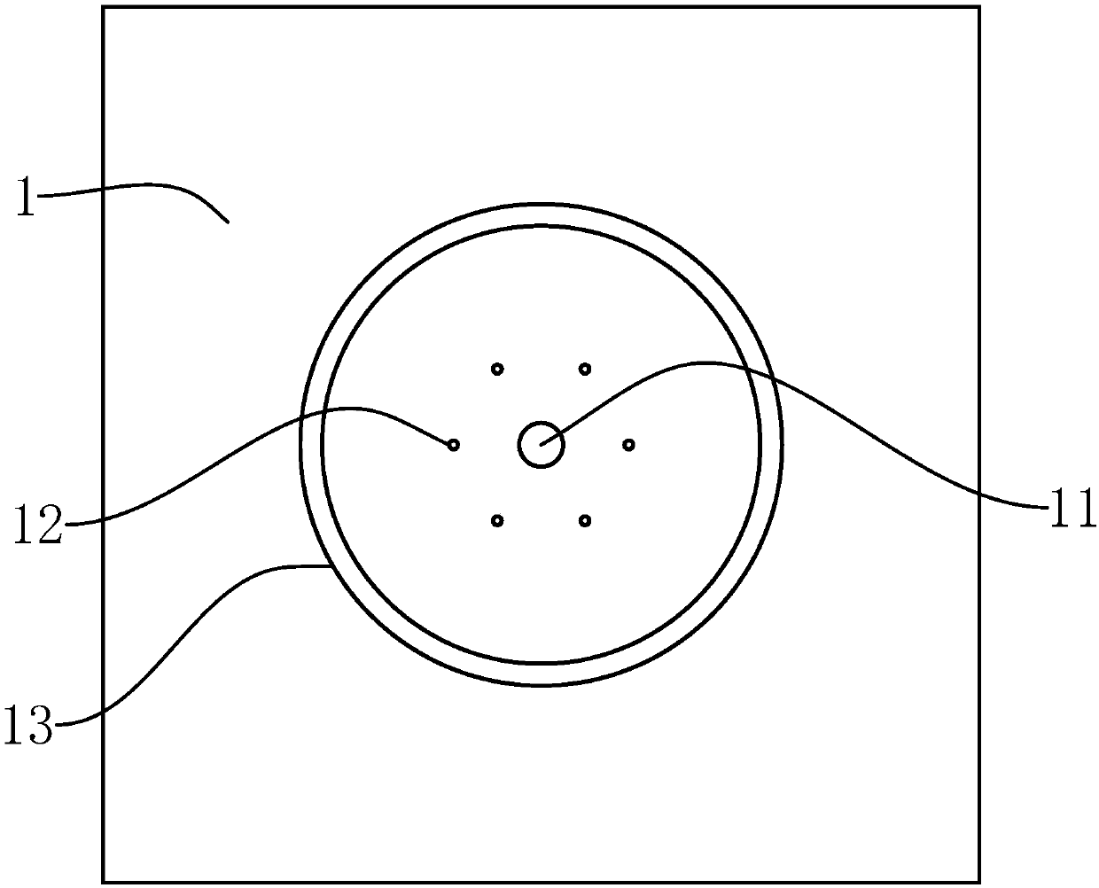
[0021] Such as Figure 1-3 As shown, the present invention has a rotary welding device, including a workbench 1 and a circular platen 2 arranged above the workbench 1. The top surface of the platen 2 is provided with several positioning holes 21 and positioning grooves 22. The top surface of the workbench 1 is There is a pin groove 11 on the surface, and the center position of the bottom surface of the table 2 is rotatably connected with a rotating shaft 23. The rotating shaft 23 is detachably inserted into the pin groove 11. There are a number of balls 24 on the bottom of the table 2, and the bottom of the ball 24 is against the top of the workbench 1. face.

[0022] Further, a number of fixing holes 12 are provided on t...


PUM


Abstract

The invention provides a rotary type welding device, and belongs to the field of welding devices. According to the device, the problem that an existing welding device is not stable in structure is solved. The rotary type welding device comprises a working table and a circular table plate arranged above the working table, a plurality of positioning holes and positioning grooves are formed in the top surface of the table plate, a pin groove is formed in the top surface of the working table, and a rotating shaft is rotationally connected to the center of the bottom surface of the table plate; andthe rotating shaft is detachably inserted into the pin groove, a plurality of balls are arranged on the bottom surface of the table plate, and the bottoms of the balls abut against the top surface ofthe working table. The bottom end of the rotating shaft is inserted into the pin groove, so that the table plate can rotate around the rotating shaft, workpieces are positioned in the positioning holes or the positioning grooves, and rotary welding can be facilitated; and meanwhile, the bottoms of the balls abut against the top surface of the working table, so that the stability of the table plate can be ensured.

Description

technical field [0001] The invention belongs to the technical field of welding devices, and relates to a rotary welding device. Background technique [0002] The existing rotary welding table can generally rotate around the rotating shaft, but generally there is only one rotating shaft connected to the bottom of the welding table, which causes the workpiece to be placed unstable on the welding table, so it is necessary to improve it. Contents of the invention [0003] The object of the present invention is to provide a rotary welding device with a stable structure to solve the above problems in the prior art. [0004] The purpose of the present invention can be achieved through the following technical solutions: a rotary welding device, characterized in that it includes a workbench and a circular platen above the workbench, and the top surface of the platen is provided with a number of positioning holes and positioning grooves , the top surface of the workbench is provide...

Claims


Application Information

Patent Timeline
Patent Type & Authority Applications(China)
IPC IPC(8): B23K37/04
CPCB23K37/0461
Inventor 王斌辉
Owner 新昌县丽晶工业产品设计有限公司
Why Eureka
Try Eureka