Connecting structure of side wall stand column and underframe boundary beam, vehicle body and rail vehicle

A technology for connecting structures and columns, applied in the field of rail vehicles, can solve problems such as reducing connection strength, and achieve the effect of improving stress conditions, meeting structural strength requirements, and solving connection strength.

Active Publication Date: 2020-06-30
CRRC TANGSHAN CO LTD
View PDF6 Cites 6 Cited by
  • Summary
  • Abstract
  • Description
  • Claims
  • Application Information

AI Technical Summary

Problems solved by technology

[0003] The embodiment of the present application provides a connection structure between the side wall column and the underframe edge beam, the car body and the rail vehicle. In the connection structure, a connecting piece is added between the sidewall column and the underframe edge beam. Increase the length of the weld between the side beams of the underframe and the side beams of the side wall, thereby improving the connection strength between the side wall columns and the side beams of the underframe, which can solve the problem of the gap between the side wall columns and the side beams of the underframe in the existing car body. The problem that the arc of the side beam cannot be welded and the connection strength is reduced

Method used


Image

  • Connecting structure of side wall stand column and underframe boundary beam, vehicle body and rail vehicle
  • Connecting structure of side wall stand column and underframe boundary beam, vehicle body and rail vehicle
  • Connecting structure of side wall stand column and underframe boundary beam, vehicle body and rail vehicle

Examples


Embodiment 1

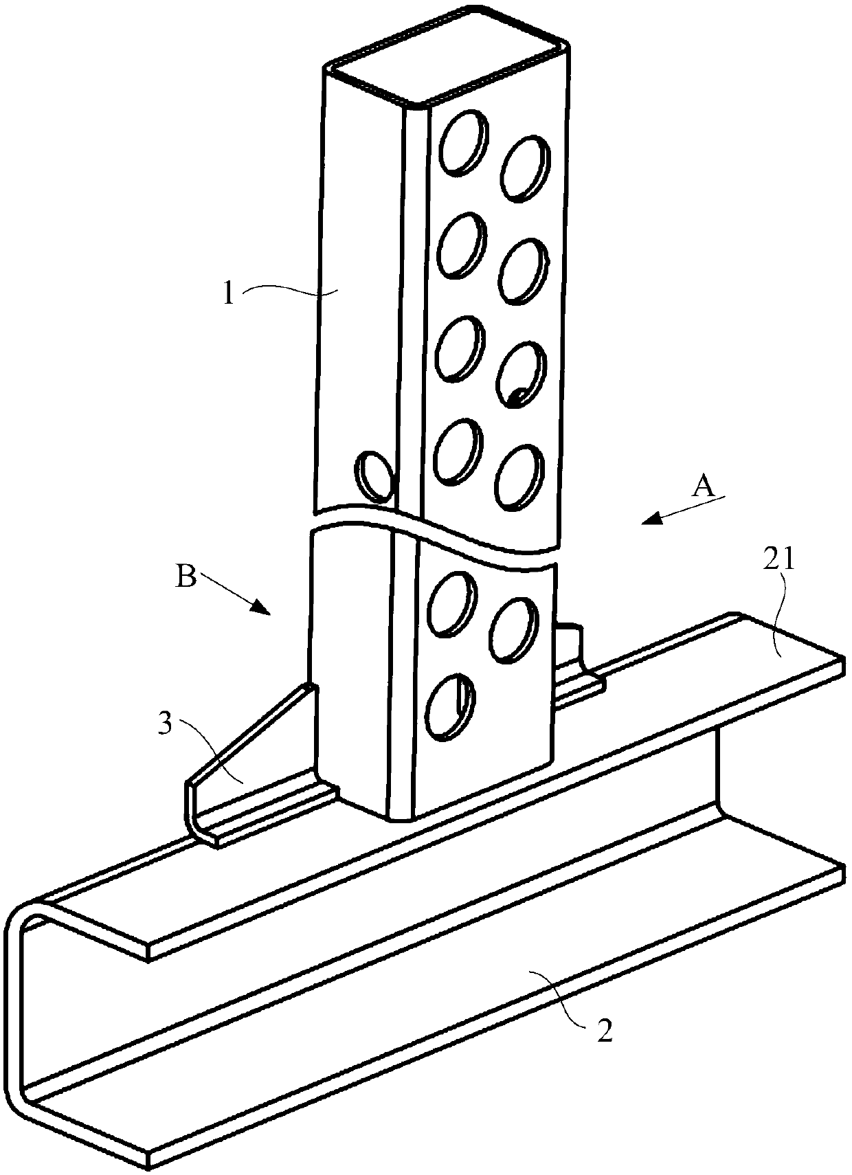
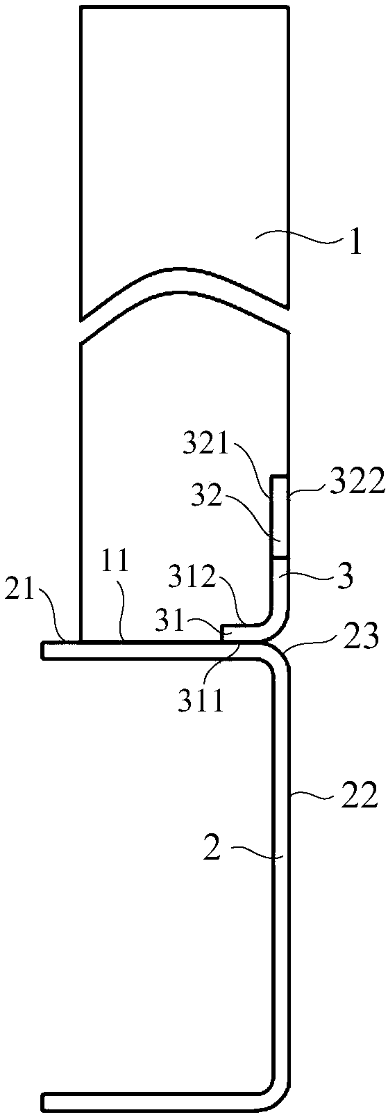
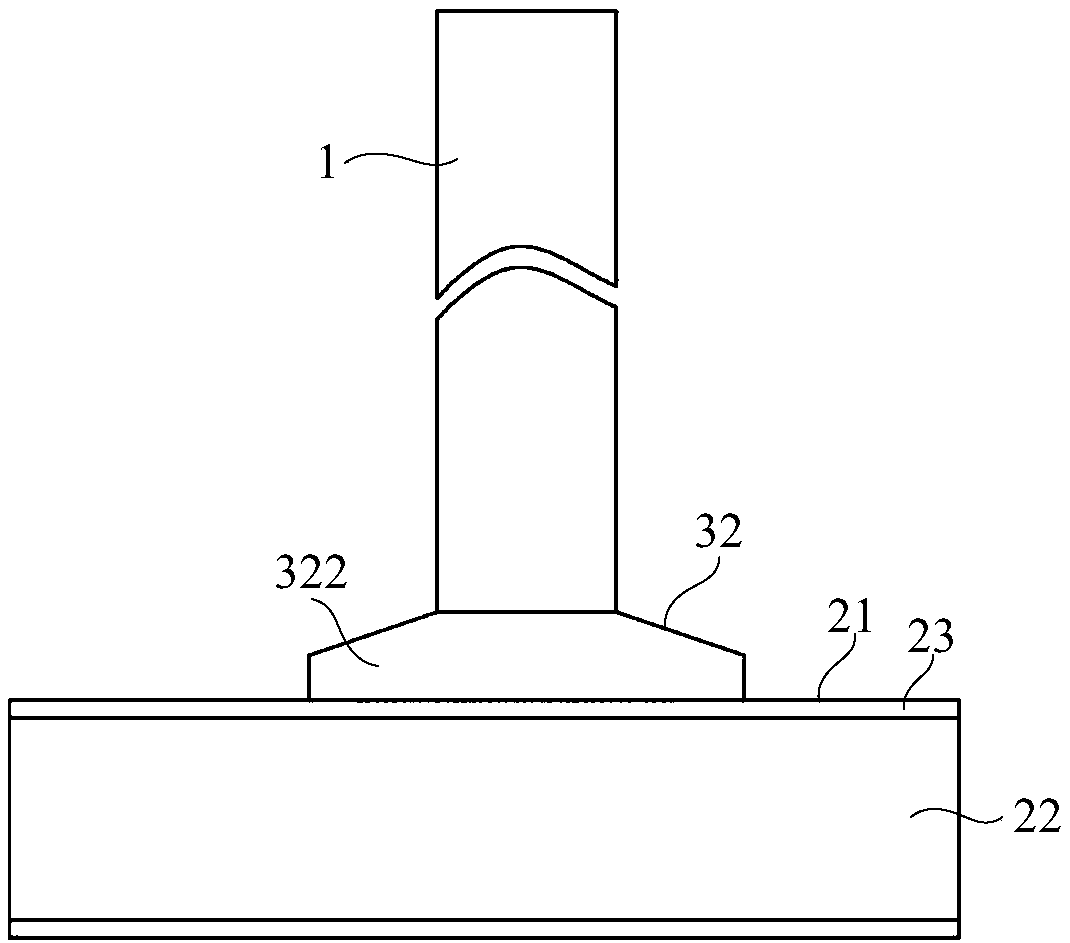
[0032] The embodiment of the present application provides a connection structure between the side wall column 1 and the underframe side beam 2, such as figure 1 with Figure 5 As shown in the structure, the connection structure includes a side wall column 1 and an underframe side beam 2, and the underframe side beam 2 is provided with a top surface 21, a side surface 22, and an arc surface 23 connecting the top surface 21 and the side surface 22; The beam 2 is a channel beam, and the top surface 21 is used to weld and connect a plurality of side wall columns 1. In order to prevent the stress concentration of the side beam 2 of the bottom frame, a rounded transition is adopted at the junction of the top surface 21 and the side surface 22, and an arc is formed. Surface 23;

[0033] The connection structure also includes a connecting piece 3 welded on the top surface 21 of the side beam 2 near the arc surface 23, the connecting piece 3 is used to enhance the connection strength ...

Embodiment 2

[0049] The embodiment of the present application provides a car body of a rail vehicle, the car body includes an underframe provided with an underframe side beam 2 and a side wall provided with a side wall column 1, and the connection between the side wall column 1 and the underframe side beam 2 Use any one of the connection structures provided in the above-mentioned embodiments for connection.

[0050] Since the above connection structure is adopted between the side wall and the chassis of the car body, a connecting piece 3 is added between the side wall column 1 and the side beam of the chassis 2, and the connection between the side wall column 1 and the chassis edge can be enlarged through the connecting piece 3. The welding area and length of the welding seam between the beams 2 can improve the connection strength between the side wall column 1 and the side beam 2 of the underframe.

Embodiment 3

[0052] An embodiment of the present application provides a rail vehicle, and the rail vehicle includes the vehicle body provided in the above embodiment.


PUM


Abstract

The embodiment of the application relates to the technical field of railway vehicles, in particular to a connecting structure of a side wall stand column and an underframe boundary beam, a vehicle body and a railway vehicle. The connecting structure comprises a side wall stand column, a bottom frame edge beam and a connecting piece welded to the side, close to the arc-shaped face, of the bottom frame edge beam. The connecting piece is used for enhancing the connecting strength between the side wall stand column and the bottom frame edge beam. One part of the bottom end face of the side wall stand column is welded to the top face of the bottom frame edge beam, and the other part of the bottom end face of the side wall stand column is welded to the connecting piece. According to the connecting structure, the connecting piece is additionally arranged between the side wall stand column and the underframe boundary beam; the length of a weld joint between the underframe boundary beam and theside wall stand column can be increased through the connecting piece, so that connecting strength between the side wall stand column and the underframe boundary beam is improved, and a problem that the connecting strength of the existing vehicle body is reduced because the side wall stand column and the underframe boundary beam cannot be welded at the arc of the underframe boundary beam can be solved.

Description

technical field [0001] The present application relates to the technical field of rail vehicles, in particular to a connection structure between a side wall column and an underframe side beam, a car body and a rail vehicle. Background technique [0002] In the car body structure of the existing rail vehicle, generally the side wall column is directly welded on the side beam of the underframe. However, when the car body needs to bear a large longitudinal compression load such as 3560kN, the weld joint between the side wall column and the side beam of the underframe needs to bear a very high load. When the side beam of the chassis of the car body adopts a grooved side beam, the corners of the side beam generally adopt a circular arc transition to prevent stress concentration. When the bottom end of the side wall column is welded to the top surface of the side beam of the chassis, Since the side beam near the side wall panel has an arc surface, the side wall column and the fram...

Claims


Application Information

Patent Timeline
Patent Type & Authority Applications(China)
IPC IPC(8): B61D17/04B61D17/08
CPCB61D17/043B61D17/08Y02T30/00
Inventor 张硕韶李志申罗超
Owner CRRC TANGSHAN CO LTD
Why Eureka
Try Eureka