Thin material laser welding method

A laser welding and thin material technology, which is applied in laser welding equipment, welding equipment, metal processing equipment, etc., can solve the problems of unreliable welding of thin material plates, and achieve increased fusion area, increased weld length, and reliable welding Effect

Pending Publication Date: 2022-04-15
SHENZHEN TETELASER TECH CO LTD
View PDF8 Cites 0 Cited by
  • Summary
  • Abstract
  • Description
  • Claims
  • Application Information

AI Technical Summary

Problems solved by technology

[0004] The main purpose of the present invention is to provide a thin material laser welding method, aiming to solve the technical problem of unreliable welding of thin material plates in the prior art

Method used


Image

  • Thin material laser welding method
  • Thin material laser welding method
  • Thin material laser welding method

Examples


specific Embodiment approach

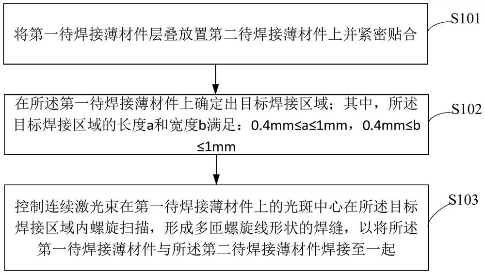
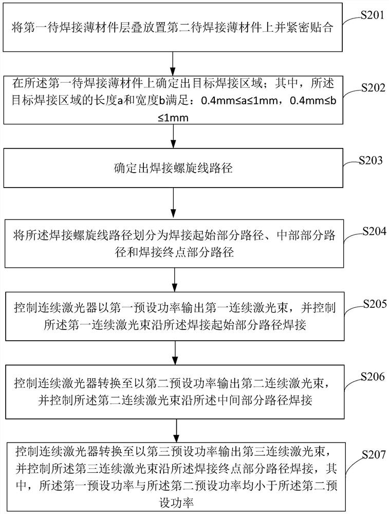
[0051] As a specific implementation manner, step S103 includes:

[0052] Controlling the spot center of the continuous laser beam on the first thin material piece to be welded starts from any point in the middle area of ​​the target welding area, and scans spirally outward in the target welding area to form a multi-turn helical line shape welds.

[0053] In this embodiment, the continuous laser beam scans from the inside of the helix to the outside, so that when the continuous laser beam scans along the welding pattern of the helix, the fusion areas on the path have the least influence on each other, thereby further improving the welding quality.

[0054] It is easy to understand that when welding thin materials, welding back marks tend to appear on the back of thin materials. For this reason, the embodiment of the present invention proposes the second embodiment of the thin material laser welding method of the present invention based on the above-mentioned embodiments. refe...


PUM

PropertyMeasurementUnit
thicknessaaaaaaaaaa

Abstract

The invention discloses a thin material laser welding method, and belongs to the technical field of welding. The method comprises the steps that a first to-be-welded thin material piece is stacked on a second to-be-welded thin material piece and tightly attached to the second to-be-welded thin material piece; a target welding area is determined on the first thin material piece to be welded; wherein the length a and the width b of the target welding area meet the conditions that a is larger than or equal to 0.4 mm and smaller than or equal to 1 mm, and b is larger than or equal to 0.4 mm and smaller than or equal to 1 mm; and a continuous laser beam is controlled to spirally scan in the target welding area in the light spot center of the first to-be-welded thin material piece, a welding seam in a multi-turn spiral line shape is formed, and the first to-be-welded thin material piece and the second to-be-welded thin material piece are welded together. According to the method, scanning is carried out along the spiral line in the extremely small target welding area, so that the length of the welding seam is increased, the fusion area of the first to-be-welded thin material piece and the second to-be-welded thin material piece is increased, and welding is firmer.

Description

technical field [0001] The invention belongs to the field of welding technology, in particular to a thin material laser welding method. Background technique [0002] In the related art, when two stacked thin material plates need to be welded together, continuous light laser welding can be used for welding. [0003] However, when continuous light laser welding is used for welding, it is easy to cause insufficient welding reliability. Contents of the invention [0004] The main purpose of the present invention is to provide a thin material laser welding method, aiming to solve the technical problem of unreliable welding of thin material plates in the prior art. [0005] In order to achieve the above object, the present invention proposes a thin material laser welding method, the method comprising: [0006] Placing the first thin material piece to be welded on top of the second thin material piece to be welded and closely adhering; [0007] A target welding area is determi...

Claims


Application Information

Patent Timeline
Patent Type & Authority Applications(China)
IPC IPC(8): B23K26/21B23K26/70B23K26/082
Inventor 吴华安韩德徐宁詹兆昂李振华张玉林杨玉松周学慧张凯
Owner SHENZHEN TETELASER TECH CO LTD
Why Eureka
Try Eureka