Engine cooling system and engine cooling control method

An engine cooling and engine technology, applied in the direction of engine cooling, coolant flow control, engine components, etc., can solve problems such as poor fuel consumption improvement, unreasonable control strategy, and unbalanced coolant temperature

Active Publication Date: 2020-06-30
GREAT WALL MOTOR CO LTD
View PDF8 Cites 4 Cited by
  • Summary
  • Abstract
  • Description
  • Claims
  • Application Information

AI Technical Summary

Problems solved by technology

[0003] The current cooling system has multiple electronic control components, whose functions are superimposed, resulting in control logic conflicts; the engine cooling system cannot operate according to the ...

Method used


Image

  • Engine cooling system and engine cooling control method
  • Engine cooling system and engine cooling control method
  • Engine cooling system and engine cooling control method

Examples


Embodiment 1

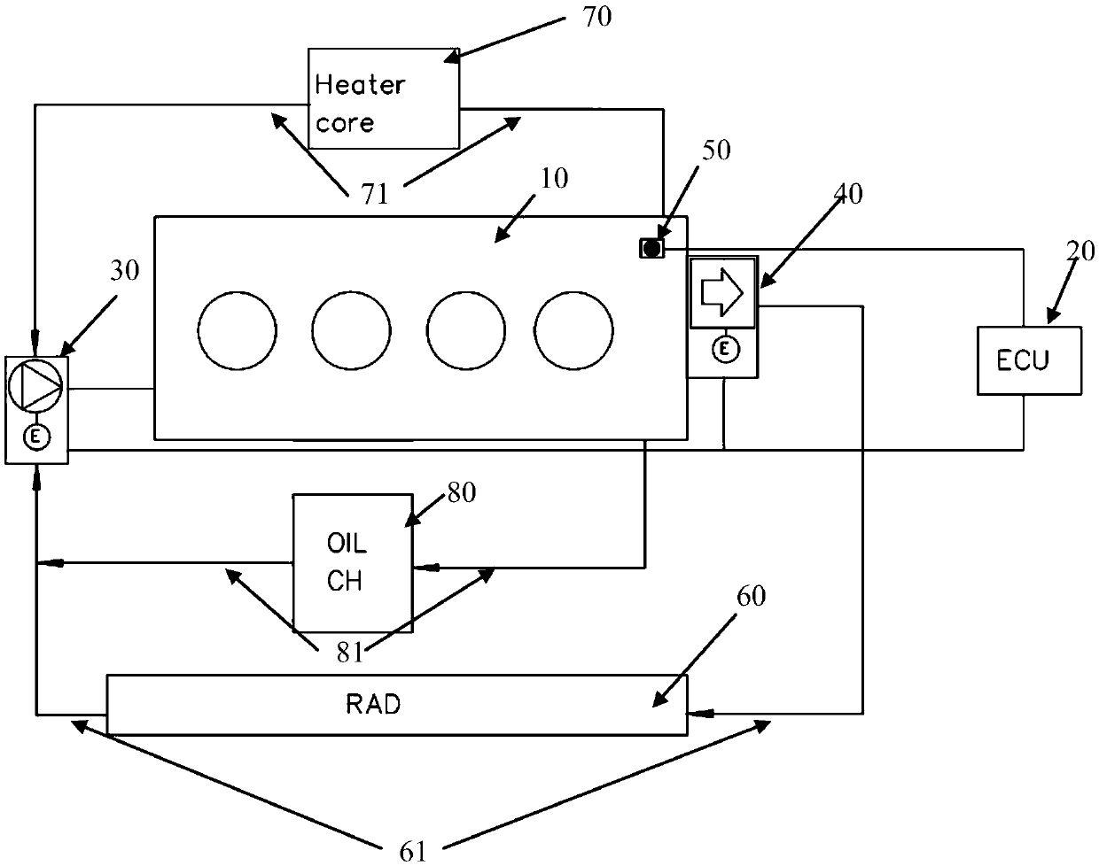
[0052] Such as figure 1 As shown, it shows a schematic diagram of an engine cooling system described in an embodiment of the present invention; the system includes:

[0053] An engine cooling system, the system includes: an engine 10 , a control module 20 , an electronic water pump 30 , an electronic thermostat 40 , a temperature sensor 50 and a cooling device 60 .

[0054] The temperature sensor 50 is arranged on the engine 10 and is electrically connected to the control module 20; the temperature sensor 50 is used to measure the current temperature of the engine 10 and transmit the current temperature to the control module 20. Module 20.

[0055] The control module 20 is electrically connected to the electronic water pump 30 and the electronic thermostat 40 respectively, and is used to control the electronic water pump 30 and the electronic thermostat 40 according to the current temperature and the first target preset temperature stored in the control module 20 . The switc...

Embodiment 2

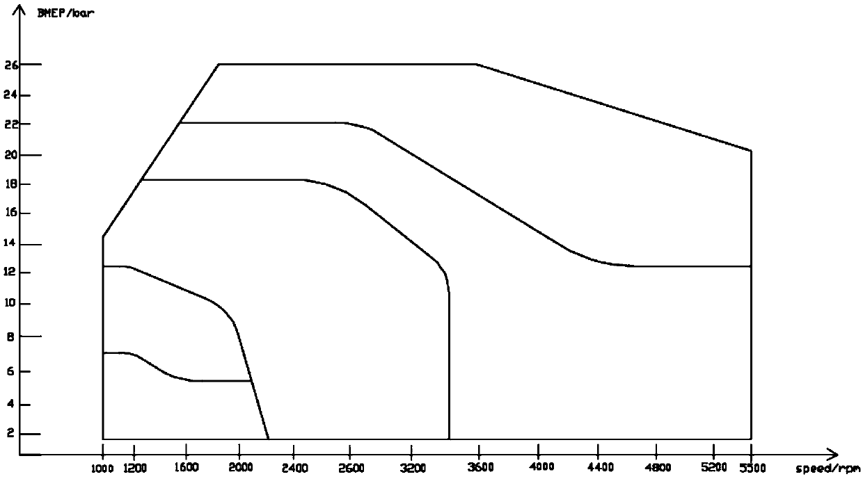
[0073] refer to figure 2 , shows a flow chart of the steps of an engine cooling control method according to an embodiment of the present invention, and the method includes the following steps:

[0074] Step 201, the control module obtains the first target preset temperature that the engine needs to reach.

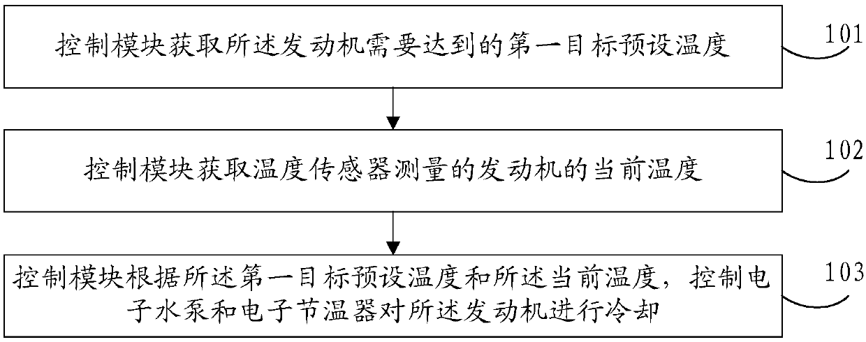
[0075] In the embodiment of the present invention, refer to image 3 , the abscissa is the rotational speed of the engine, and the ordinate is the average effective pressure of the engine at different temperatures, wherein the greater the average effective pressure, the stronger the engine's working ability.

[0076] In the embodiment of the present invention, the control module can obtain the first target preset temperature corresponding to the rotation speed of the engine according to the rotation speed of the engine. The first preset target temperature is the temperature at which the average effective pressure of the engine is maximized at a specified rotational speed...

Embodiment 3

[0084] refer to Figure 4 , shows a flow chart of the steps of an engine cooling control method according to an embodiment of the present invention, and the method includes the following steps:

[0085] Step 301, the control module acquires the first target preset temperature that the engine needs to reach.

[0086] In the embodiment of the present invention, when the engine is in a stopped state, both the electronic thermostat and the electronic water pump are closed, that is, the cooling system does not work, and when the engine is started, the electronic thermostat and the electronic water pump are turned off. Also set to off.

[0087] In the embodiment of the present invention, when the engine is cold started, a first target preset temperature to be reached by the engine is acquired, wherein the first target preset temperature is preset by the control module. For example, it is preset that when the engine starts cold, the first target preset temperature to be reached is ...


PUM


Abstract

The invention provides an engine cooling system and a control method thereof. The system comprises an engine, a control module, an electronic water pump, an electronic thermostat, a temperature sensorand a heat dissipation device; the temperature sensor is arranged on the engine and electrically connected with the control module; the temperature sensor is used for measuring the current temperature of the engine and transmitting the current temperature to the control module; the control module is electrically connected with the electronic water pump and the electronic thermostat and used for controlling starting and stopping of the electronic water pump and the opening degree of the electronic thermostat according to the current temperature and first target preset temperature stored in thecontrol module to enable the current temperature to reach the first target preset temperature; and the electronic thermostat is used for controlling the flow of heat dissipation fluid in a first water way. According to the engine cooling system, control over the cooling system can be accurately achieved through few electronic components, and the engine always works at the proper temperature.

Description

technical field [0001] The invention relates to the technical field of engine cooling, in particular to an engine cooling system and an engine cooling control method. Background technique [0002] As the core component of the vehicle, the engine keeps the engine working at a suitable temperature, which can reduce the fuel consumption and emissions of the vehicle. When the engine is working, it will generate a lot of heat, which will increase its temperature, so its cooling is very important. . [0003] The current cooling system has multiple electronic control components, whose functions are superimposed, resulting in control logic conflicts; the engine cooling system cannot operate according to the set temperature, and the improvement of fuel consumption is poor; there are also unreasonable control strategies, unbalanced coolant temperature, and low coolant temperature Or high, so that there is a quality risk in the engine. Contents of the invention [0004] In view of ...

Claims


Application Information

Patent Timeline
IPC IPC(8): F01P7/16
CPCF01P7/16F01P7/162F01P2050/22
Inventor 常培松张春辉刘刚曹永伟赵华崔鹏程夏朝辉徐天博魏永强门帅石鹏伟王浩张瑞铺
Owner GREAT WALL MOTOR CO LTD
Why Eureka
Try Eureka