Automatic speed clutch

A clutch and rotational speed technology, applied in the direction of automatic clutch, clutch, mechanical equipment, etc., can solve the problems of generator and its auxiliary equipment damage, unstable power supply, etc., to achieve the effect of low application environment requirements, low manufacturing cost, and simple structure

Inactive Publication Date: 2020-06-30
NANJING MEIXUE POWER TECH
View PDF0 Cites 0 Cited by
  • Summary
  • Abstract
  • Description
  • Claims
  • Application Information

AI Technical Summary

Problems solved by technology

[0002] There are many types of clutches, which are applied to various mechanical equipment to achieve the purpose of transmission and protection; but with the development of human beings, more and more attention is paid to environmental protection, and the demand for energy is also increasing. Using clean and renewable New energy has become an inevitable choice for human beings. Therefore, wind power and wave power generation are becoming more and more popular. However, due to the frequent changes in the size of wind and waves, the speed of the generator is constantly changing, and too high speed will cause the generator and its auxiliary The equipment is damaged. In order to solve this problem, people generally disconnect the line manually or by computer to stop power generation. Unstable; the traditional clutch is generally designed according to the size of the load, and it is for overload protection. Therefore, an automatic clutch is needed now, which can automatically protect the generator and other equipment in time and automatically according to the change of the speed

Method used


Image

  • Automatic speed clutch
  • Automatic speed clutch
  • Automatic speed clutch

Examples


Embodiment Construction

[0029] to attach figure 1 - attached Figure 20 For example:

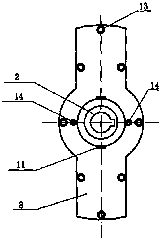
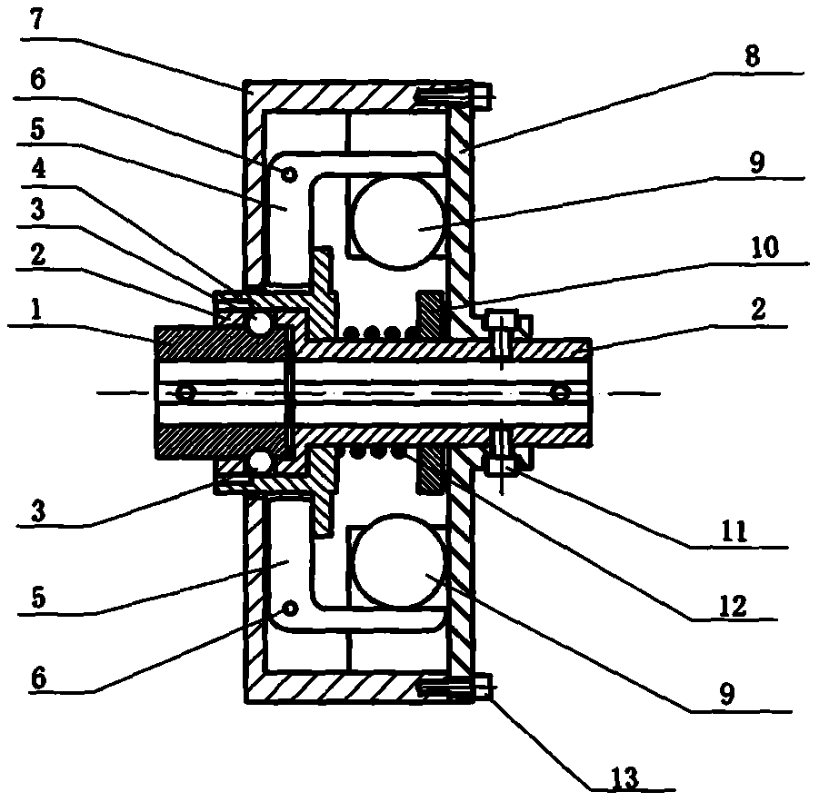
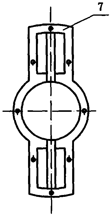
[0030] The present invention includes housing 7, input shaft sleeve 2, output shaft sleeve 1, pressure sleeve 4, push rod 5, cover plate 8, centrifugal ball 9, pressure ball 3, compression spring 12, slide plate 10 ten parts; Push rod 5 is "L" shape, is installed in described casing 7 by push rod installation shaft 6, and described push rod 5 can rotate around described push rod installation shaft 6, and several described push rods 5 are relative to all The center of the housing 7 is symmetrically arranged, and a centrifugal ball 9 is placed under the small end of each of the push rods 5; 12. The sliding plate 10 and the cover plate 8, the input shaft sleeve 2 with various components installed are installed in the middle of the housing 7, the end surface of the protrusion 19 of the pressure sleeve 4 is in contact with the pusher The big ends of the rods 5 are close together, the cover plate 8 is fixed together w...


PUM


Abstract

The invention provides an automatic speed clutch. The automatic speed clutch comprises 10 parts including a shell, an input shaft sleeve, an output shaft sleeve, a pressing sleeve, push rods, a coverplate, centrifugal balls, a pressing ball, a pressure spring and a sliding disc. Each push rod is in an L shape, the push rods are mounted in the shell through a shaft, the push rods can rotate aroundthe shaft, the push rods are symmetrically arranged relative to the center of the shell, and the centrifugal balls are correspondingly arranged below the small ends of the push rods. The input shaftsleeve is mounted in the middle of the shell, the end surface of a convex block of the pressing sleeve abuts against the big ends of the push rods, the output shaft sleeve is mounted in a large port of the input shaft sleeve, and a groove matched with the pressing ball is arranged on the output shaft sleeve. The pressing ball is placed in a pressing ball hole of the input shaft sleeve.

Description

technical field [0001] The invention relates to a novel rotational speed clutch. Background technique [0002] There are many types of clutches, which are applied to various mechanical equipment to achieve the purpose of transmission and protection; but with the development of human beings, more and more attention is paid to environmental protection, and the demand for energy is also increasing. Using clean and renewable New energy has become an inevitable choice for human beings. Therefore, wind power and wave power generation are becoming more and more popular. However, due to the frequent changes in the size of wind and waves, the speed of the generator is constantly changing, and too high speed will cause the generator and its auxiliary The equipment is damaged. In order to solve this problem, people generally disconnect the line manually or by computer to stop power generation. Unstable; traditional clutches are generally designed according to the size of the load and ...

Claims


Application Information

Patent Timeline
Patent Type & Authority Applications(China)
IPC IPC(8): F16D43/16
CPCF16D43/16F16D2043/145
Inventor 唐红兵
Owner NANJING MEIXUE POWER TECH
Why Eureka
Try Eureka