Device for collecting and removing gases in an aluminum electrolysis cell

A gas gathering and gas technology, applied in the field of non-ferrous metallurgy, can solve problems such as the inability to ensure the removal of electrolytic gas

Active Publication Date: 2020-06-30
OBSHCHESTVO S OGRANICHENNOY OTVETSTVENNOSTYU OBEDINENNAYA KOMPANIYA RUSAL INZHENERNO TEKHNOLOGICHESKIY TSENTR
View PDF12 Cites 0 Cited by
  • Summary
  • Abstract
  • Description
  • Claims
  • Application Information

AI Technical Summary

Problems solved by technology

[0015] Therefore, prior art devices do not ensure effective removal of electrolyzed gases both between and during normal operation of the reduction tank operation

Method used


Image

  • Device for collecting and removing gases in an aluminum electrolysis cell
  • Device for collecting and removing gases in an aluminum electrolysis cell
  • Device for collecting and removing gases in an aluminum electrolysis cell

Examples


Embodiment Construction

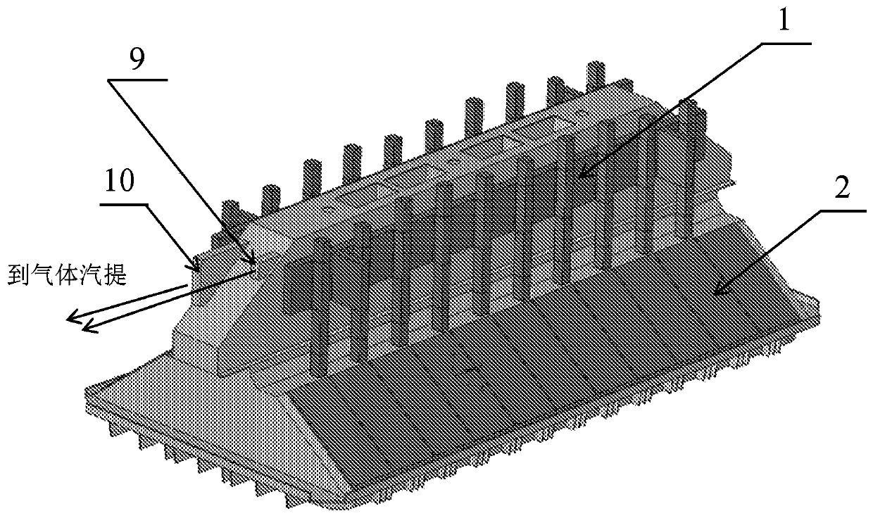
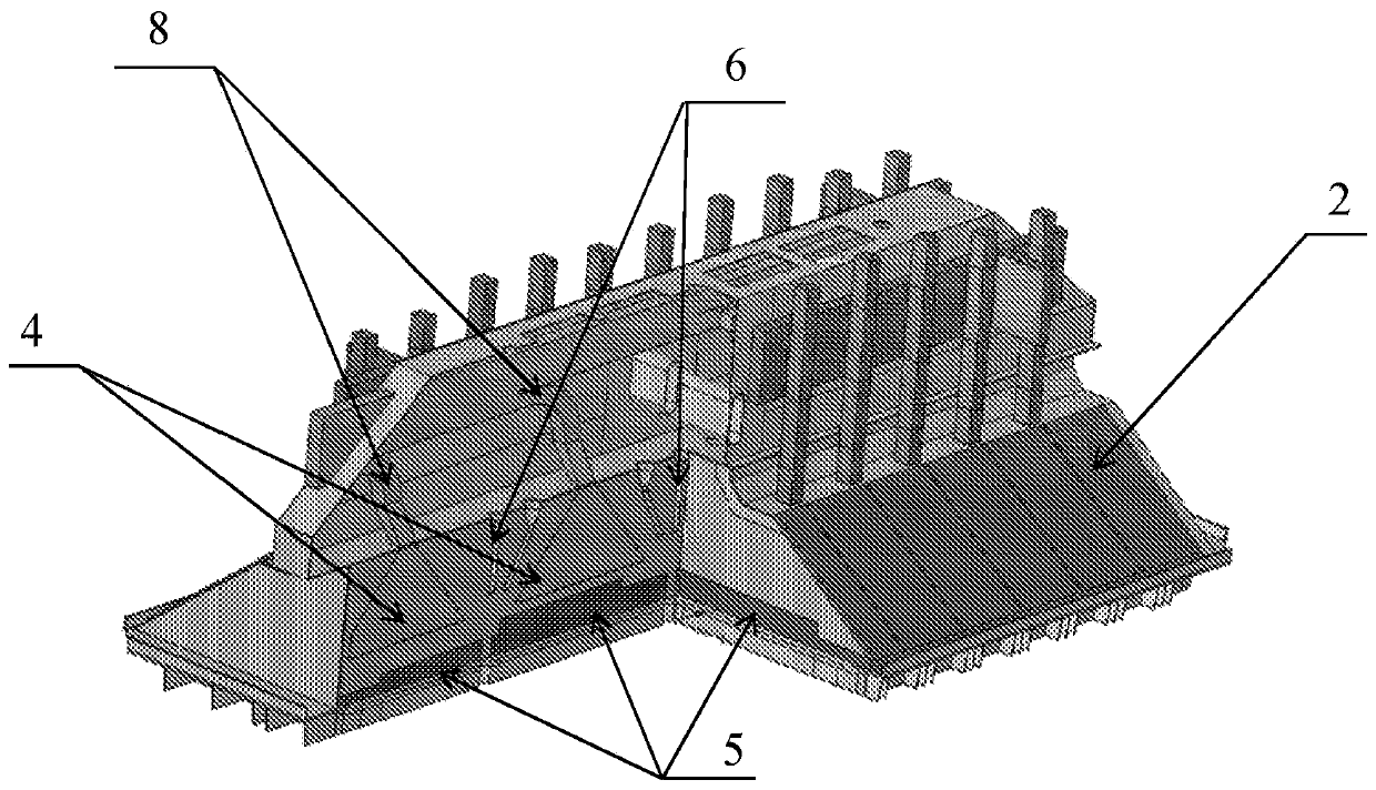
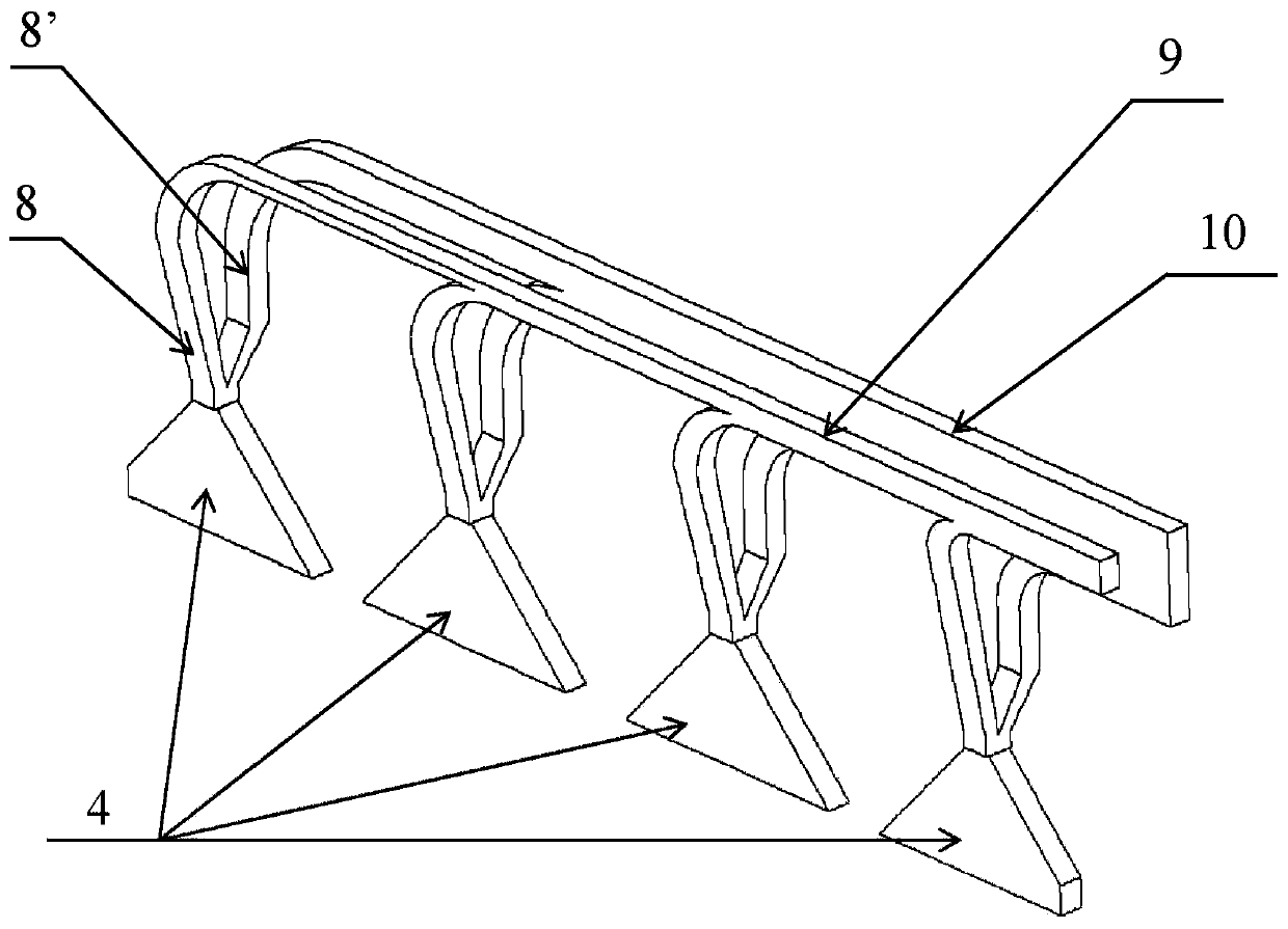
[0040] Devices for collecting and removing gases are installed in the reduction tank. A reduction tank is a device for the production of aluminum by reducing a melt and typically consists of an anode, a point alumina feeder with a breaker, a collector beam with gas lines and caps, and a hood. All structural elements of the claimed device are fixed on the collector beam 1 . The cover of the reduction tank 2 is made of a separate cover, inside which the guide element 3 is firmly mounted horizontally with respect to the electrolyte casing of the melt. Guiding elements can be structured as plates or protrusions ( Figure 4 and Figure 5 ), the plate or protrusion is made of the material used to make the cover, such as aluminum. The number of guide elements is determined by the velocity of the flow between the guides, and it is necessary to ensure that the airflow velocity is higher than 2m / s and lower than 7m / s to exclude the gas escaping from the reduction tank and carry the a...


PUM


Abstract

The invention relates to the production of aluminum in electrolysis cells with baked anodes. A device comprises a system of gas ducts and gas-collecting caps. Each of the caps is connected by a firstchannel to a horizontal gas duct so as to form a main gas removal circuit, and is connected by a second channel to an additional gas duct so as to form an additional gas removal circuit. The height ofeach subsequent channel of the main loop is increased by 16-24% of the height of the preceding channel, and the height of each subsequent channel of the additional loop is increased by 24-26% of theheight of the preceding channel. Separator plates are mounted inside the caps. The length of each subsequent plate is reduced with respect to the preceding by 25-35%. The technical effect is to reducethe volumes of gases removed from the electrolysis cell, and to maintain gas removal efficiency.

Description

technical field [0001] The present invention relates to non-ferrous metallurgy, and in particular to the production of aluminum in reduction tanks with prebaked anodes, and can be used to reduce the amount of gas removed from the reduction tank while conventionally Removal efficiencies are maintained high between runs and during routine operation. Background technique [0002] Devices are known in which the air collecting cap is in contact with the housing at the housing opening. The purpose of this invention is to collect exhaust gases from reduction tanks in order to remove them from aluminum fluorine compounds (patent US 4,770,752, 1988). [0003] Disadvantages of the known device include the limitations of said invention related to maintenance of the alumina feed system located inside the cap and possible damage during anode replacement due to the cap's location close to the anode and casing. [0004] An arrangement is known in which a standard amount of process gas is...

Claims


Application Information

Patent Timeline
IPC IPC(8): C25C3/22
CPCC25C3/22
Inventor V·G·沙德林Y·A·特蕾特雅科夫A·S·热尔杰夫
Owner OBSHCHESTVO S OGRANICHENNOY OTVETSTVENNOSTYU OBEDINENNAYA KOMPANIYA RUSAL INZHENERNO TEKHNOLOGICHESKIY TSENTR
Why Eureka
Try Eureka