Aircraft buffer variable damping oil needle

A buffer and variable damping technology, applied in shock absorbers, shock absorbers, mechanical equipment, etc., can solve the problems of energy absorption affecting buffers, monotonous variable damping parameter curves, low buffer efficiency, etc., and achieve efficiency coefficients. Improvement, significant technical effect, full power curve effect

Active Publication Date: 2016-01-13
XIAN AIRCRAFT DESIGN INST OF AVIATION IND OF CHINA
View PDF8 Cites 0 Cited by
  • Summary
  • Abstract
  • Description
  • Claims
  • Application Information

AI Technical Summary

Problems solved by technology

[0002] For ordinary small aircraft buffer damping devices, the damping device in the form of a single oil hole is generally used, but for large aircraft buffers, the efficiency of the single oil hole damper is low, and the oil needle variable damping device is generally used. The oil needle variable damping device can Improve the efficiency of the buffer, but what kind of variable damping coefficient can maximize the efficiency of the buffer has not been studied in depth
[0003] At present, domestic and foreign small aircraft buffers use a single oil hole damping device, the damping parameter is a constant, and the vertical load curve has a sag between the two peaks, which affects the energy absorption of the buffer, resulting in low efficiency of the buffer
For the oil needle damping device mainly used in large aircraft buffers, the lower end of the oil needle is fixed in the piston rod, the oil needle has a smooth conical cross-section, and the gap between the oil needle and the plunger forms the oil passing area of ​​the damping device. For this variable damping The structural form of the device, the variable damping parameter curve is monotonous, which cannot fully improve the efficiency of the variable damping buffer, and it is difficult to adjust the variable damping parameter during the drop test, requiring repeated repairs

Method used


Image

  • Aircraft buffer variable damping oil needle
  • Aircraft buffer variable damping oil needle
  • Aircraft buffer variable damping oil needle

Examples


Embodiment Construction

[0016] Below in conjunction with accompanying drawing and embodiment the present invention will be further described:

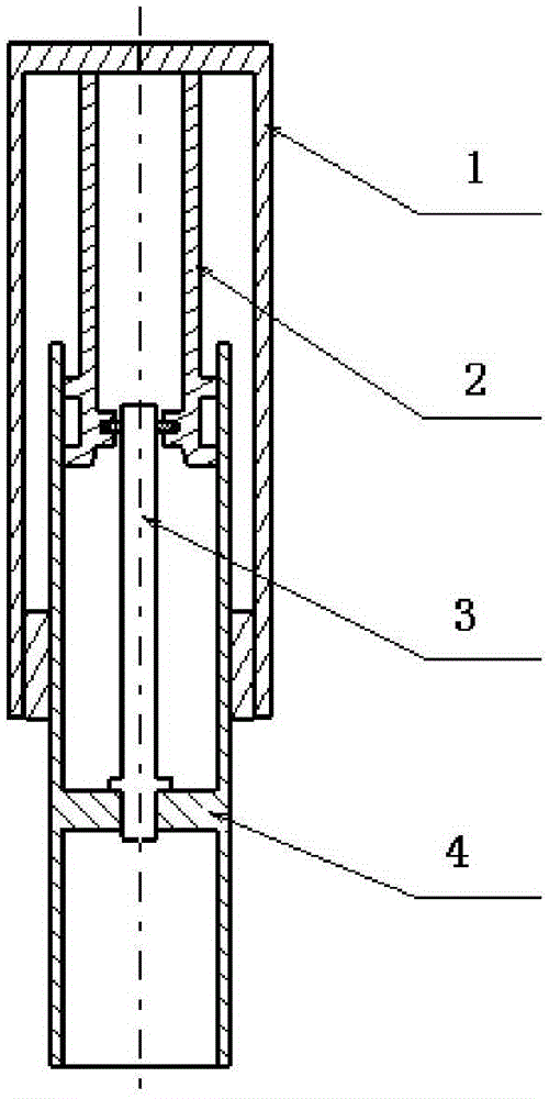
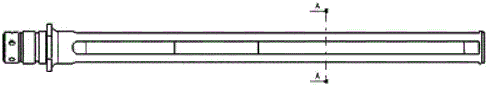
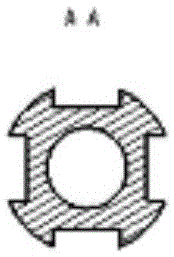
[0017] see figure 1 , which is a schematic diagram of the installation structure of the variable damping oil needle of the aircraft buffer of the present invention. The variable damping oil needle of the aircraft buffer of the present invention, its lower end is installed inside the piston rod 4, and its upper end is inserted into the plunger 2 to form a buffer damping device together. When the buffer is compressed, the piston rod 4 and the oil needle 3 are quickly inserted into the outer Inside the barrel 1, the oil in the piston rod quickly flows through the groove on the surface of the needle body of the oil needle to generate a damping force. The variable damping oil needle of the aircraft buffer of the present invention is a cylindrical needle body. see figure 2 , the outer surface of the needle is provided with several longitudinally distributed gro...


PUM


Abstract

The invention belongs to an airplane buffer technology, and relates to a variable damping oil needle of an airplane buffer. The variable damping oil needle of the airplane buffer is a cylindrical needle body, and a plurality of grooves which are longitudinally distributed are formed in the outer surface of the needle body. From an initial segment, the four grooves used as control points are axially formed on the outer surface of the needle body, wherein the parameter of the sectional area of the oil needle on the initial segment is 1.07f. The first groove is located in the 0.27L position, wherein the parameter of the sectional area of the oil needle is 1.07f. The second groove is located in the 0.57L position, wherein the parameter of the sectional area of the oil needle is 0.96f. The third groove is located in the 0.8L position, wherein the parameter of the sectional area of the oil needle is 0.615f. The fourth groove is located in the 0.9L position, wherein the parameter of the sectional area of the oil needle is 0.48f. The parameter of the sectional area of the oil needle at the tail end is 0.3f. L is the structural stroke of the buffer, and f is the set oil hole area generated when two peak values of a perpendicular load are kept equal. According to the variable damping oil needle of the airplane buffer, a sunken area between the two peak values of the perpendicular load can be eliminated, the load becomes gentle, a work amount curve of the buffer is full, efficiency coefficients are increased to 80% and far exceed efficiency coefficients in an existing level, and the remarkable technical effect is achieved.

Description

technical field [0001] The invention belongs to the aircraft buffer technology, and relates to a variable damping oil needle of the aircraft buffer. Background technique [0002] For ordinary small aircraft buffer damping devices, the damping device in the form of a single oil hole is generally used, but for large aircraft buffers, the efficiency of the single oil hole damper is low, and the oil needle variable damping device is generally used. The oil needle variable damping device can Improve the efficiency of the buffer, but what kind of variable damping coefficient can maximize the efficiency of the buffer has not been studied in depth. [0003] At present, small aircraft buffers at home and abroad use a single oil hole damping device. The damping parameter is a constant, and the vertical load curve has a sag between the two peaks, which affects the energy absorption of the buffer, resulting in low efficiency of the buffer. For the oil needle damping device mainly used ...

Claims


Application Information

Patent Timeline
Patent Type & Authority Patents(China)
IPC IPC(8): F16F9/34
Inventor 朱永健张万民张立军
Owner XIAN AIRCRAFT DESIGN INST OF AVIATION IND OF CHINA
Why Eureka
Try Eureka