Finger fixing device for hand and foot surgical nursing
A fixation device and surgical technique, applied in the direction of stereotaxic surgical instruments, etc., can solve the problems of poor comfort and inability to adjust the angle of fingers apart
- Summary
- Abstract
- Description
- Claims
- Application Information
AI Technical Summary
Problems solved by technology
Method used
Image

Examples
Embodiment Construction
[0022] The following will clearly and completely describe the technical solutions in the embodiments of the present invention with reference to the accompanying drawings in the embodiments of the present invention. Obviously, the described embodiments are only some, not all, embodiments of the present invention.
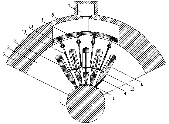
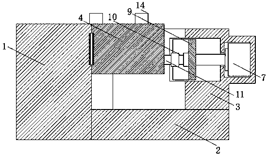
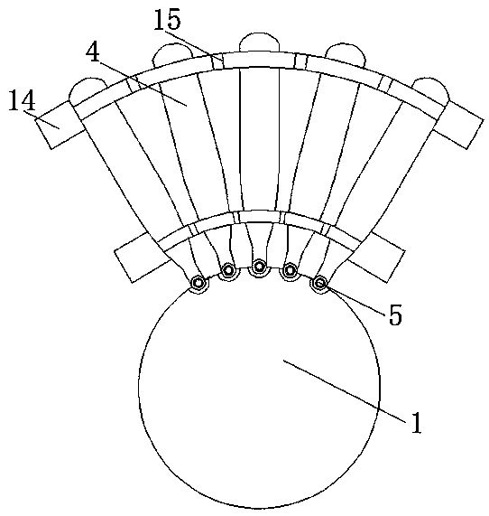
[0023] refer to Figure 1-3 , a finger fixation device for hand and foot surgery care, comprising a cylinder 1, an arc-shaped disc 2 is fixedly connected to the rear side of the cylinder 1, an arc-shaped platform 3 is fixedly connected to the outer surface of the arc-shaped disc 2, and an arc-shaped platform 3 is fixedly connected to the rear side of the cylinder 1. A plurality of support plates 4 are provided, a first hinge 5 is arranged between the support plates 4 and the cylinder 1, a slide rail 6 is provided on the support plates 4, a push rod motor 7 is provided on the rear side of the arc table 3, and the arc table The inner wall of 3 is provided with chute 8,...
PUM
 Abstract
Description
Claims
Application Information
 - Generate Ideas
- Intellectual Property
- Life Sciences
- Materials
- Tech Scout
- Unparalleled Data Quality
- Higher Quality Content
- 60% Fewer Hallucinations
Browse by: Latest US Patents, China's latest patents, Technical Efficacy Thesaurus, Application Domain, Technology Topic, Popular Technical Reports.
© 2025 PatSnap. All rights reserved.Legal|Privacy policy|Modern Slavery Act Transparency Statement|Sitemap|About US| Contact US: help@patsnap.com