Shaft end grinding and polishing device and method

A shaft end and equipment technology, which is applied in the field of shaft end grinding and polishing equipment, can solve the problems of low work efficiency, high labor intensity of operators, and inability to meet the processing needs of large batches, and achieve the effect of ensuring the grinding effect

Active Publication Date: 2020-07-03
CHINA THREE GORGES UNIV
View PDF5 Cites 2 Cited by
  • Summary
  • Abstract
  • Description
  • Claims
  • Application Information

AI Technical Summary

Problems solved by technology

[0002] During the processing of shaft parts, the shaft ends need to be ground and polished. The current grinding process is mainly carried out by manual hand-held grinding, and manual grinding is used. The work efficiency is relatively low, and the labor intensity of the operators High, unable to meet the processing needs of large quantities

Method used


Image

  • Shaft end grinding and polishing device and method
  • Shaft end grinding and polishing device and method

Examples


Embodiment 1

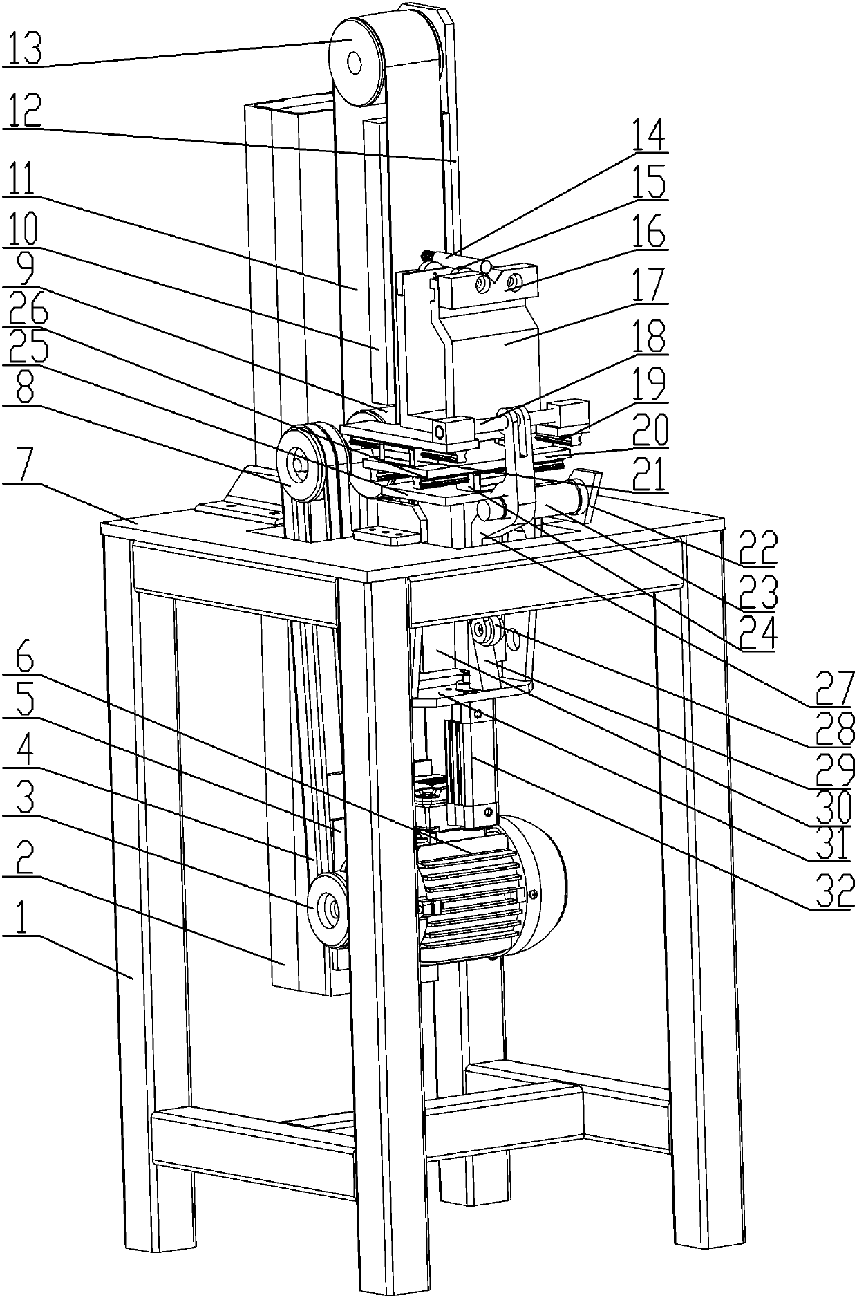
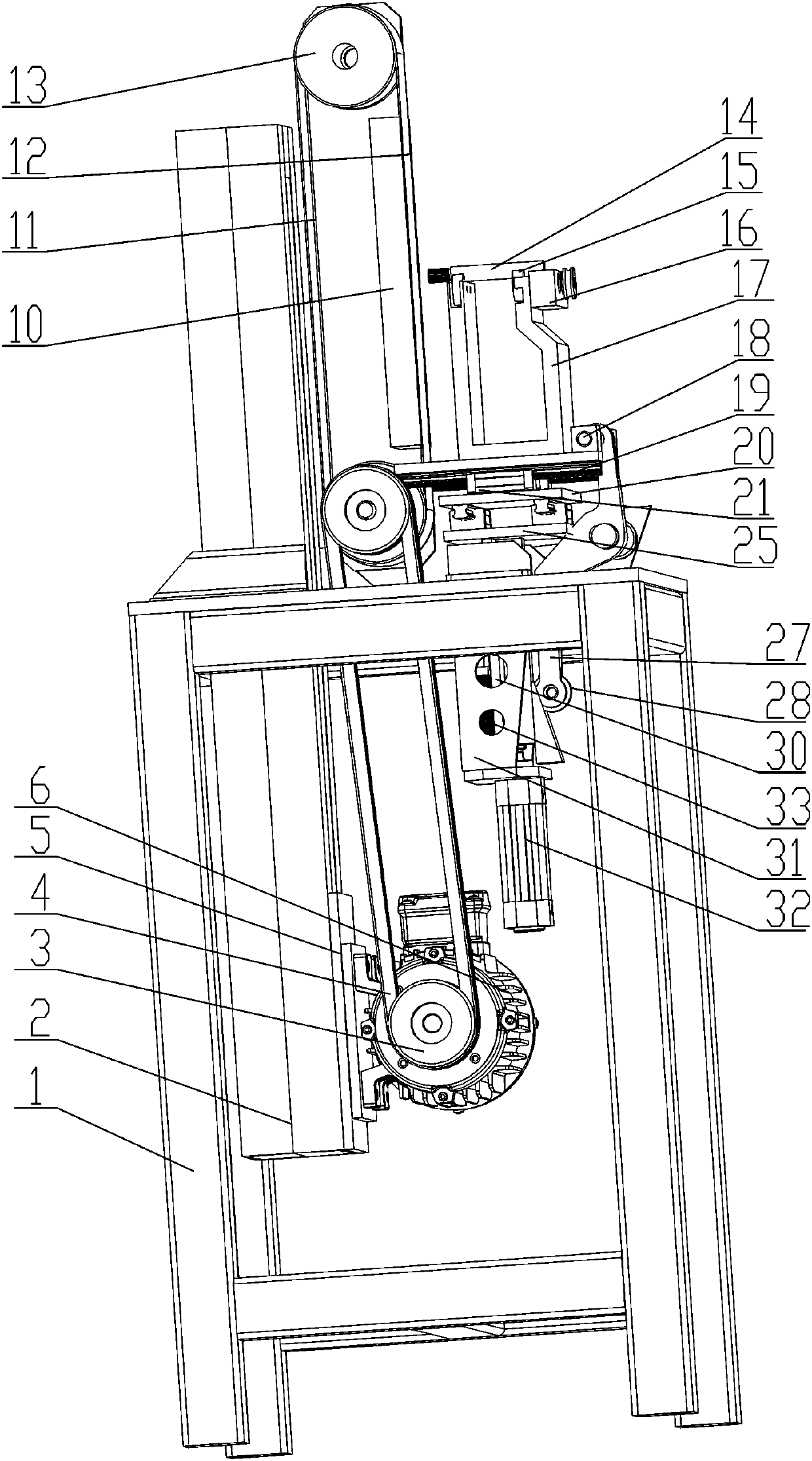
[0031] see Figure 1-2 , shaft end grinding and polishing equipment, which includes a frame 1, a column 2 is fixedly installed on the frame 1, a polishing belt mounting plate 12 is fixedly installed on the upper part of the column 2, and a useful The grinding belt device is used for grinding, and the grinding belt device is connected with the grinding power device for driving it to rotate. The top plate 7 is fixedly installed on the top of the frame 1, and the lifting box 31 is fixedly installed on the bottom end of the top plate 7. , the lifting box 31 is equipped with a lifting mechanism, the top of the lifting mechanism is fixedly equipped with a lifting top plate 25, and the top of the lifting top plate 25 is fixedly installed with a two-axis slide mechanism for horizontal and vertical movement. The top of the shaft slide mechanism is fixedly equipped with a clamping seat 17 for fixing shaft parts, and a cam type grinding feed mechanism for driving it close to the grinding...

Embodiment 2

[0040] The method for grinding the shaft end by the shaft end grinding and polishing equipment comprises the following steps:

[0041] Step1: Fix the shaft part 14 to be polished on the top of the clamping seat 17 through the top clamp, and fix it through the V-shaped positioning plate 16;

[0042] Step2: Start the grinding power device, drive the driving pulley 3 through the motor 6, drive the belt 4 through the driving pulley 3, drive the driven pulley 8 through the belt 4, and drive the grinding belt device through the driven pulley 8;

[0043] Step3: Drive the grinding belt 11 through the second roller 9 of the grinding belt device;

[0044] Step4: Restart the lifting mechanism, drive the vertical lifting plate 30 to lift along the vertical guide rail 33 through the lifting cylinder 32, and then drive the lifting top plate 25 to rise through the vertical lifting plate 30, and then drive the two shafts on the top through the lifting top plate 25 The sliding table mechanism...


PUM


Abstract

The invention provides a shaft end grinding and polishing device and method. A stand column is fixedly installed on a rack, a grinding belt installing plate is fixedly installed on the upper portion of the stand column, a grinding belt device used for conducting grinding is installed on the grinding belt installing plate, and the grinding belt device is connected with a grinding power device usedfor driving the grinding belt device to rotate; and a top plate is fixedly installed on the top of the rack, a lifting box body is fixedly installed on the end face of the bottom of the top plate, a lifting mechanism is installed on the lifting box body, a lifting top plate is fixedly installed on the top of the lifting mechanism, a biaxial sliding platform mechanism for achieving transverse and longitudinal moving is fixedly installed on the top of the lifting top plate, a clamping base used for fixing shaft type parts is fixedly installed on the top of the biaxial sliding platform mechanism,and a cam type grinding feeding mechanism used for driving the clamping base to be close to the grinding belt device is installed between the clamping base and the lifting mechanism. The polishing equipment can be used for grinding and polishing the shaft ends of the shaft type parts, and then a traditional manual grinding mode is replaced.

Description

technical field [0001] The invention belongs to the field of grinding devices, in particular to equipment and methods for grinding and polishing shaft ends. Background technique [0002] During the processing of shaft parts, the shaft ends need to be ground and polished. The current grinding process is mainly carried out by manual hand-held grinding, and manual grinding is used. The work efficiency is relatively low, and the labor intensity of the operators High, unable to meet the processing needs of large quantities. Contents of the invention [0003] In order to solve the above technical problems, the present invention provides shaft end grinding and polishing equipment and methods. The polishing equipment can be used for grinding and polishing the shaft ends of shaft parts, thereby replacing the traditional manual grinding method and greatly improving the grinding efficiency. [0004] In order to achieve the above-mentioned technical features, the object of the presen...

Claims


Application Information

Patent Timeline
Patent Type & Authority Applications(China)
IPC IPC(8): B24B21/00B24B21/18B24B47/20B24B41/06B24B41/02B24B41/00B24B1/00
CPCB24B1/00B24B21/002B24B21/18B24B41/00B24B41/02B24B41/06B24B47/20
Inventor 董元发王蕾刘文戎张存吉张文厉严华兵蒋磊
Owner CHINA THREE GORGES UNIV
Why Eureka
Try Eureka