
Assembling and disassembling structure for main machine and cutter rest and handheld tool

A tool holder and host technology, applied in the direction of manufacturing tools, portable mobile devices, etc., can solve the problems of affecting operation, small tolerance, small contact area, etc., and achieve the effect of convenient operation, easy operation and good stability

Pending Publication Date: 2020-07-03
ZHEJIANG DESHI ELECTRICAL APPLIANCE CO LTD
View PDF0 Cites 6 Cited by
  • Summary
  • Abstract
  • Description
  • Claims
  • Application Information

AI Technical Summary

Problems solved by technology

[0004] However, in this structure, it takes a lot of force to make the elastic clamp expand and withdraw from the clamping groove, which requires relatively high strength for the user's fingers, and there is no change for users such as women.
[0005] In addition, the elastic clamp is a metal wire or a metal sheet, which has a small contact area with the tool holder, a small tolerance, and relatively weak fixing stability. There is a certain vibration of the tool holder during work, which affects the operation.

Method used


Image

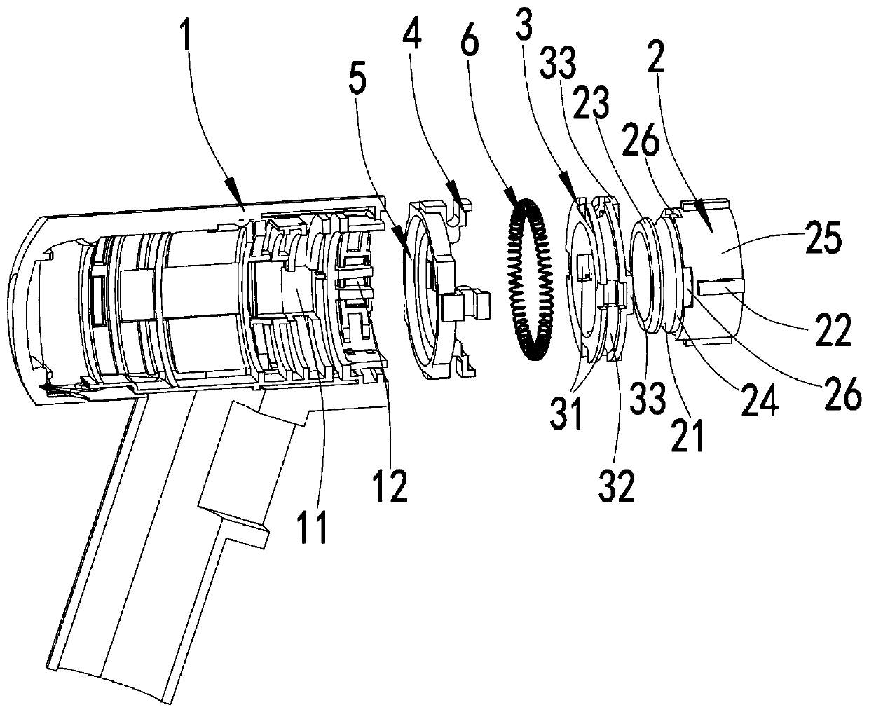
  • Assembling and disassembling structure for main machine and cutter rest and handheld tool
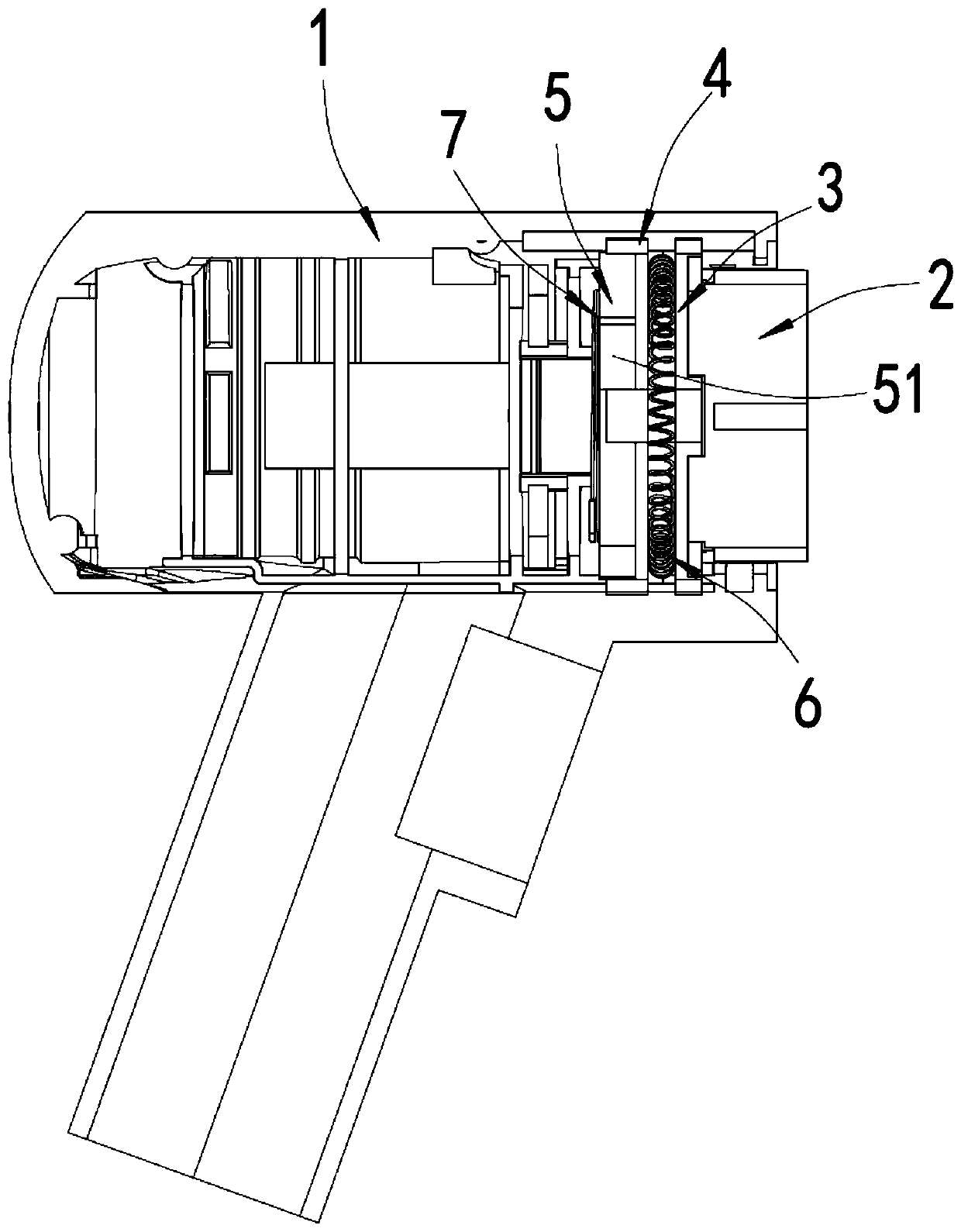
  • Assembling and disassembling structure for main machine and cutter rest and handheld tool
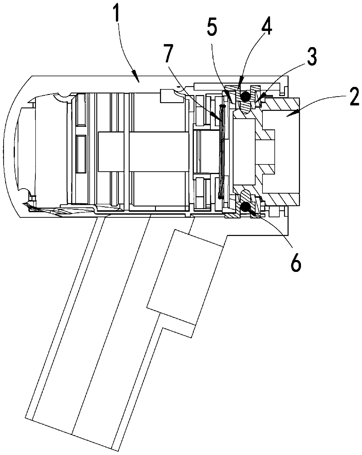
  • Assembling and disassembling structure for main machine and cutter rest and handheld tool

Examples


Embodiment Construction

[0046] Objects, advantages and features of the present invention will be illustrated and explained by the following non-limiting description of preferred embodiments. These embodiments are only typical examples of applying the technical solutions of the present invention, and all technical solutions formed by adopting equivalent replacements or equivalent transformations fall within the protection scope of the present invention.

[0047] In the description of the scheme, it should be noted that the terms "center", "upper", "lower", "left", "right", "front", "rear", "vertical", "horizontal", " The orientation or positional relationship indicated by "inner", "outer", etc. is based on the orientation or positional relationship shown in the drawings, and is only for the convenience of description and simplification of description, rather than indicating or implying that the device or element referred to must have a specific orientation , constructed and operated in a particular or...


PUM


Abstract

The invention discloses an assembling and disassembling structure for a main machine and a cutter rest and a handheld tool. The assembling and disassembling structure for the main machine and the cutter rest comprises a main shell and an auxiliary shell detachably connected with the main shell. The auxiliary shell achieves rapid locking and unlocking with the main shell through matching between alocking ring, multiple lock buckles and a drive ring in the main shell and a locking groove on the auxiliary shell. By manually rotating the drive ring, the multiple lock buckles can be driven to switch between a third position and a fourth position; when the lock buckles are located at the third position, the lock buckles are embedded into the locking groove of the auxiliary shell to achieve locking; and when the lock buckles are located at the fourth position, the lock buckles retreat from the locking groove, and then locking of the auxiliary shell can be eliminated, and disassembly can be conducted. The assembling and disassembling structure adopts a rotary knob type unlocking structure, during unlocking, the situation that pressing is conducted hard to enable an elastic hoop to expandis not needed, and operation is easy; by the adoption of the assembling and disassembling structure for the main machine and the cutter rest, during installation, it is just needed to insert the auxiliary shell, pressing a button is not needed, the requirement for a user is low, and operation is convenient; and the locking stability of the assembling and disassembling structure for the main machine and the cutter rest is good.

Description

technical field [0001] The invention relates to the field of electric tools, in particular to the assembly and disassembly structure of a main engine and a knife holder and a hand-held tool. Background technique [0002] Hand-held tools control the start and stop of the motor through the start and stop buttons, so that the motor torque is transmitted to the drill bit, saw, grinding disc, hammer and other components through a certain torsion transmission structure, so that the drill bit, saw, turntable, etc. can rotate, reciprocate, stretch or Devices that vibrate, etc. [0003] As the types and functions of hand-held tools become more and more abundant, users usually need to purchase hand-held tools with corresponding functions to meet certain usage needs, which increases the user's cost of use. Given that the driving structures of these hand-held tools are basically similar, Therefore, there is a structure that can be detachably assembled with a variety of different types ...

Claims


Application Information

Patent Timeline
IPC IPC(8): B25F5/00
CPCB25F5/00
Inventor 李跃辉钟志民龙啸
Owner ZHEJIANG DESHI ELECTRICAL APPLIANCE CO LTD
Learn More