Automatic continuous stamping device for multi-page file

A page document and automatic technology, which is applied in the field of automatic continuous stamping devices, can solve the problems of high time consumption, high labor intensity and low work efficiency.

Inactive Publication Date: 2020-07-03
温州天炽包装有限公司
View PDF0 Cites 2 Cited by
  • Summary
  • Abstract
  • Description
  • Claims
  • Application Information

AI Technical Summary

Problems solved by technology

[0003] At present, when affixing the official seal or other seals, it is often manually affixed. For the case of a large number of contracts or document scores, manually affixing the official seal one by one will obviously consume a lot of time and improve work efficiency. It is not high, and the labor intensity is relatively high. There is no automatic equipment in the market that can perform continuous page turning and stamping

Method used


Image

  • Automatic continuous stamping device for multi-page file
  • Automatic continuous stamping device for multi-page file
  • Automatic continuous stamping device for multi-page file

Examples


Embodiment 1

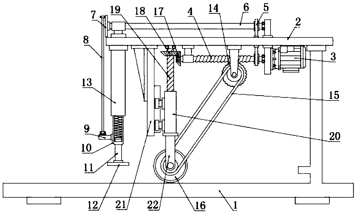
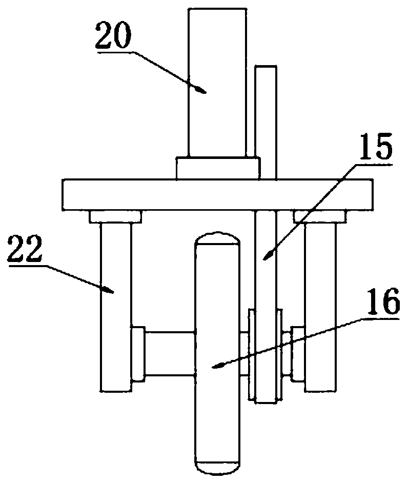
[0022] see Figure 1~3 , in an embodiment of the present invention, an automatic continuous stamping device for multi-page documents includes a main frame 1, a worm 4, a movable sleeve 10, a seal 12, a page turning wheel 16 and a screw 19; the main frame 1 The top plate 2 is fixed on the top, and the drive motor 3 is fixedly installed under one side of the top plate 2. The output end of the drive motor 3 is connected to the worm 4 in rotation. The worm 4 is connected to the shaft 6 through the transmission belt 5. The shaft 6 is connected to the top of the top plate 2 in rotation. Yes, the top plate 2 is provided with a through hole for the transmission belt 5 to pass through, and the drive motor 3 is connected to the power supply and the switch with a lead. After the switch is turned on, the drive motor 3 is energized to drive the worm 4 to rotate, and the worm 4 uses the transmission belt 5 to drive the rotating shaft 6 to rotate; The end of the rotating shaft 6 is fixedly c...

Embodiment 2

[0026] In order to further explain the above-mentioned automatic continuous stamping device for multi-page documents, this application provides another embodiment, the automatic continuous stamping device for multi-page documents in this embodiment has the following technical features: The four corners are all fixed with pads, and the side wall of the main frame 1 is provided with a raised portion that limits the free end of the file. The drive motor 3 is a servo motor that can be forward and reverse at the output end. Between the raised part and the seal 12, then turn on the motor switch to work, press the switch reversely after the work is completed so that the worm screw 4 reverses and the page turning wheel 16 is slowly lifted to facilitate the next work.

[0027] According to the specific description of the above-mentioned embodiments, it is easy to know that the working principle of the present invention is: after the switch is turned on, the drive motor 3 is energized to...


PUM


Abstract

The invention discloses an automatic continuous stamping device for a multi-page file, and particularly relates to a device which drives an elastic rod with elasticity and a stamp to move up and downin a reciprocating mode through a movable sleeve for stamping and meanwhile drives a worm wheel and a bevel gear set to rotate through a rotating worm. A rotating shaft is rotationally connected abovea top plate, the end of the rotating shaft is fixedly connected with a rotating disc, the side edge of the rotating disc is rotationally connected with the upper end of a connecting rod, the lower end of the connecting rod is rotationally connected with a fixed block, the fixed block is fixed to the lower side wall of the movable sleeve, and the upper part of the movable sleeve is sleeved with the lower part of a fixed sleeve; the elastic rod is sleeved with the lower part of the movable sleeve, and the lower end of the elastic rod is fixedly connected with the stamp; the worm wheel meshes below the worm, the worm wheel is connected with a page turning wheel through a synchronous belt, the page turning wheel is rotationally connected to a support, and the support is arranged below the topplate; and the end of the worm is fixedly connected with a first bevel gear, the first bevel gear meshes with a second bevel gear, and the second bevel gear is fixed to the upper portion of a screw rod.

Description

technical field [0001] The invention relates to an office stationery, in particular to an automatic continuous stamping device for multi-page documents. Background technique [0002] The business activities of enterprises often involve some regulatory documents and contract documents. Such documents often need to be affixed with the corporate seal, stamped on documents, paper, calligraphy and painting works, etc., and stamped with patterns or lettering to show confirmation Or inspection and approval are the most common office work. [0003] At present, when affixing the official seal or other seals, it is often manually affixed. For the case of a large number of contracts or document scores, manually affixing the official seal one by one will obviously consume a lot of time and improve work efficiency. Not high, labor intensity is bigger, also does not exist a kind of automation equipment that can carry out continuous page turning and stamping on the market. Contents of t...

Claims


Application Information

Patent Timeline
Patent Type & Authority Applications(China)
IPC IPC(8): B41K3/04B41K3/62
CPCB41K3/04B41K3/62
Inventor 不公告发明人
Owner 温州天炽包装有限公司
Why Eureka
Try Eureka