Deep thick hard rock underground continuous wall grooving construction method and structure

A technology for underground continuous wall and grooved construction, which is applied in basic structure engineering, drilling equipment and methods, excavation, etc., can solve the problem of difficulty in controlling the verticality of secondary holes, difficulty in repairing holes with square hammer impact, and long processing time for partial holes. and other problems, to achieve the effect of improving the level of safety and civilization, reducing the operation of punching pile drivers, and simplifying the on-site management process.

Inactive Publication Date: 2020-07-03
SHENZHEN GONGKAN GEOTECHN GRP +1
View PDF6 Cites 1 Cited by
  • Summary
  • Abstract
  • Description
  • Claims
  • Application Information

AI Technical Summary

Problems solved by technology

It is difficult to control the verticality of secondary holes in rotary excavation or percussion pilot holes, and it takes a long time to process partial holes; the number of pilot holes is small or the pilot holes are deviated, which brings greater difficulties to square hammer impact hole repair, and the overall performance is that the construction progress is slow , the comprehensive cost is high; especially the impact drilling speed is slow, in order to maintain the construction progress, generally two percussion drilling rigs will be driven in a slot to guide or repair the hole at the same time, and the cross operation will bring a greater safety hazard

Method used


Image

  • Deep thick hard rock underground continuous wall grooving construction method and structure
  • Deep thick hard rock underground continuous wall grooving construction method and structure
  • Deep thick hard rock underground continuous wall grooving construction method and structure

Examples


Embodiment Construction

[0037] The idea, specific structure and technical effects of the present invention will be clearly and completely described below in conjunction with the embodiments and accompanying drawings, so as to fully understand the purpose, features and effects of the present invention. Apparently, the described embodiments are only some of the embodiments of the present invention, rather than all of them. Based on the embodiments of the present invention, other embodiments obtained by those skilled in the art without creative efforts belong to The protection scope of the present invention. In addition, all the connection / connection relationships involved in the patent do not simply refer to the direct connection of components, but mean that a better connection structure can be formed by adding or reducing connection accessories according to specific implementation conditions. The various technical features in the invention can be combined interactively on the premise of not conflictin...


PUM


Abstract

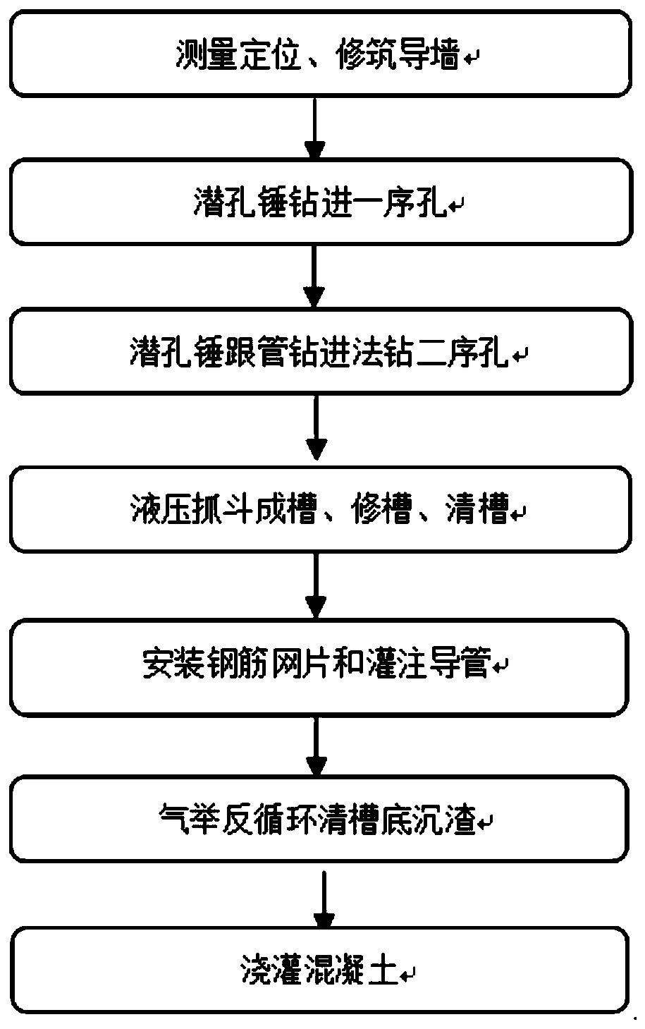
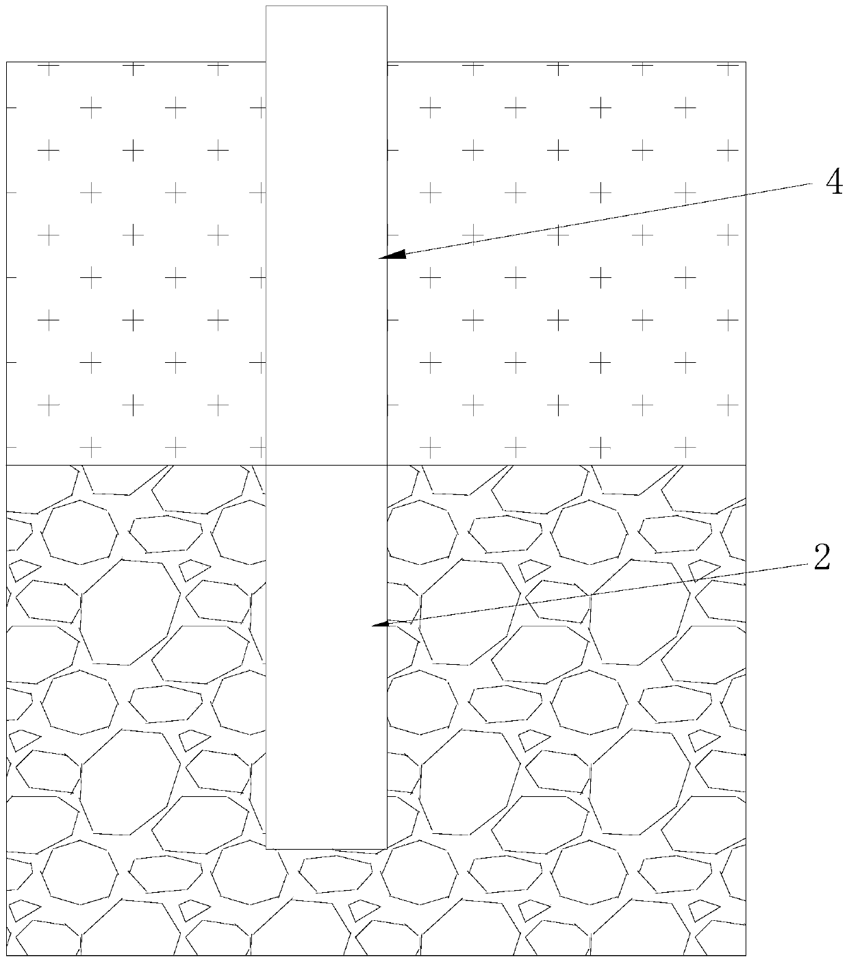
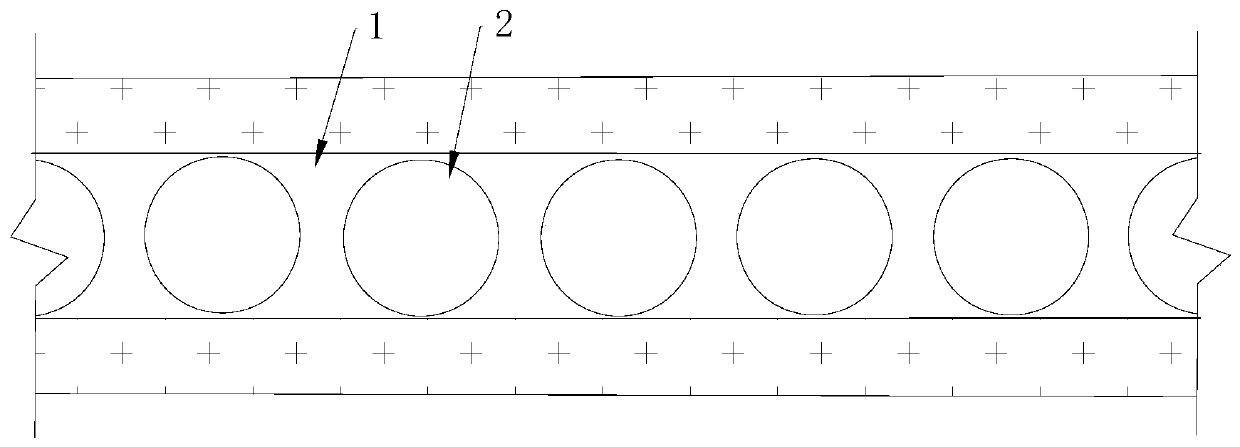
The invention relates to the technical field of underground continuous wall grooving, in particular to a deep thick hard rock underground continuous wall grooving construction method. The method comprises the following steps of first, measuring, positioning and constructing a guide wall; second, performing wall protection on a soil layer at the upper part by adopting a wall protective sleeve first, then drilling into the wall protective sleeve by adopting a down-the-hole hammer, drilling into a rock layer to a designed elevation, repeating the steps above, and drilling a plurality of first guide holes which are arranged adjacently; third, drilling a second guide hole between adjacent two first guide holes by adopting a down-the-hole hammer with pipe drilling method, and communicating the second guide hole with the adjacent two first guide holes to form a groove; fourth, trimming the groove and cleaning the groove by adopting a hydraulic grabbing bucket; fifth, mounting reinforcing meshpieces and grouting a guide pipe; and sixth, grouting concrete. The construction method disclosed by the invention is high in hole guiding speed; moreover, a hole is not required to be trimmed by adopting an impact plane set-hammer after the hole is guided; processes are reduced; and the construction efficiency is higher.

Description

technical field [0001] The invention relates to the field of timely groove formation of an underground diaphragm wall, in particular to a construction method and a structure thereof for groove formation of an underground diaphragm wall with deep and thick hard rock. Background technique [0002] When deep rock formations are encountered during the trenching construction of the underground diaphragm wall, rotary drilling rigs are generally used to core the pilot holes sequentially, or the cross hammer of the punching pile machine is used to impact the pilot holes, and then the impact square hammer is used to repair the holes. It is difficult to control the verticality of secondary holes in rotary excavation or percussion pilot holes, and it takes a long time to process partial holes; the number of pilot holes is small or the pilot holes are deviated, which brings greater difficulties to square hammer impact hole repair, and the overall performance is that the construction prog...

Claims


Application Information

Patent Timeline
Patent Type & Authority Applications(China)
IPC IPC(8): E02D5/20E02D17/06E02D17/08E02D7/18E21B1/00E21B7/04E21B21/16
CPCE02D5/20E02D7/18E02D17/06E02D17/08E21B1/00E21B7/04E21B21/16
Inventor 尚增弟邹俊峰雷斌侯雷莫森升黄晓凯孔德健沙桢晖
Owner SHENZHEN GONGKAN GEOTECHN GRP
Why Eureka
Try Eureka