A slurry type pressure taking pipe

A pressure-taking pipe and slurry technology, which is applied in the direction of measuring fluid pressure, instruments, measuring devices, etc., can solve the problems of pressure-taking port blockage, pressure-taking instrument erosion and wear, etc., to avoid erosion, improve stability, and avoid blockage Effect

Active Publication Date: 2022-01-28
SHANDONG ZHANGQIU BLOWER
View PDF0 Cites 0 Cited by
  • Summary
  • Abstract
  • Description
  • Claims
  • Application Information

AI Technical Summary

Problems solved by technology

[0003] The technical task of the present invention is to provide a slurry-type pressure-taking pipe for the deficiencies in the above-mentioned prior art. This kind of slurry-type pressure-taking pipe effectively solves the erosion and wear of the pressure-taking instrument in the slurry environment, and Blockage of the pressure tap

Method used


Image

  • A slurry type pressure taking pipe
  • A slurry type pressure taking pipe

Examples


Embodiment Construction

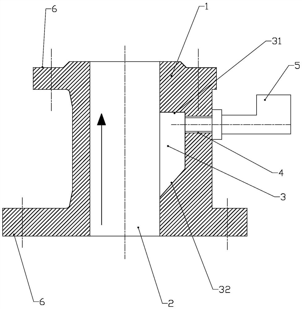
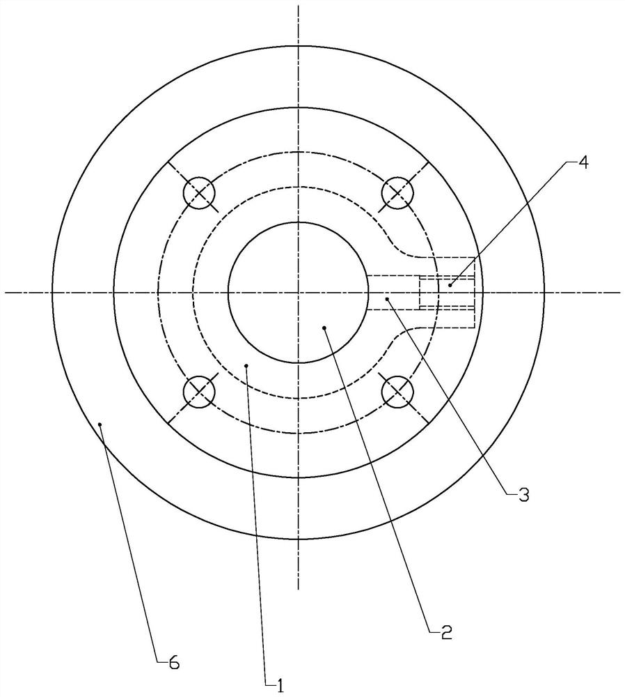
[0017] Refer to the attached figure 1 And attached figure 2 A slurry-type pressure-taking pipe of the present invention will be described in detail below.

[0018] A slurry-type pressure-taking pipe of the present invention has a structure comprising a pressure-taking pipe body 1. The central opening of the pressure-taking pipe body 1 is a main channel 2, and a pressure-taking groove 3 is arranged on the inner wall. The groove 3 communicates with the main channel 2, and the pressure taking pipe body 1 outside the pressure taking groove 3 is provided with a pressure taking instrument connection port 4, and the pressure taking instrument connection port 4 is connected with the pressure taking groove 3, and the pressure taking instrument The instrument connection port 4 is connected with a pressure measuring instrument 5 .

[0019] The pressure-taking groove 3 is a rectangular bar shape, and the upper part is a straight corner opening 31, which effectively prevents the high-sp...


PUM

PropertyMeasurementUnit
angleaaaaaaaaaa
angleaaaaaaaaaa

Abstract

The invention discloses a slurry-type pressure-taking pipe, which belongs to the pressure-taking pipe. Its structure includes a pressure-taking pipe body. The pressure taking groove is connected with the main channel, and the pressure taking pipe body outside the pressure taking groove is provided with a pressure taking instrument connection port, the pressure taking instrument connection port is connected with the pressure taking groove, and the pressure taking instrument connection port is connected with a pressure taking instrument. pressure instrument. Compared with the prior art, the slurry-type pressure-taking pipe of the present invention effectively solves the problems of scouring and wear of pressure-taking instruments and blockage of pressure-taking ports in a slurry environment.

Description

technical field [0001] The invention relates to a pressure-taking pipe, in particular to a slurry-type pressure-taking pipe. Background technique [0002] With the development of the Internet and Internet of Things technology, the safety of industrial devices and intelligent monitoring are increasingly demanding, and intelligent fluid equipment is also developing in it. Due to the characteristics of impurities in slurry fluid equipment, the use of pressure measuring instruments has been unstable. , when taking pressure, because the pressure taking head of the pressure taking instrument is directly inserted into the fluid pipeline, the slurry fluid directly washes the pressure taking head, which seriously wears the pressure taking head. In addition, impurities are easy to block the pressure taking port, affecting Intelligent monitoring is restricted, which restricts the development of intelligent fluid equipment. Contents of the invention [0003] The technical task of the...

Claims


Application Information

Patent Timeline
Patent Type & Authority Patents(China)
IPC IPC(8): G01L19/06
CPCG01L19/06G01L19/0627
Inventor 杨晓斌部辉李曰森邵焕
Owner SHANDONG ZHANGQIU BLOWER
Why Eureka
Try Eureka