Hearth temperature water-cooling control device for large circulating fluidized bed boiler

A technology of circulating fluidized bed and control device, which is applied in the direction of fluidized bed combustion equipment, combustion type, fuel burned in melting state, etc. It can solve problems such as difficult control of furnace temperature and high furnace temperature, and improve the aerodynamic field , Improve the heat exchange intensity and prolong the service life

Inactive Publication Date: 2016-05-18
SHANXI GUOFENG COAL POWER CO LTD +1
View PDF4 Cites 0 Cited by
  • Summary
  • Abstract
  • Description
  • Claims
  • Application Information

AI Technical Summary

Problems solved by technology

[0003] The purpose of the present invention is to overcome the deficiencies of the above-mentioned prior art, and propose a large-scale circulating fluidized bed boiler furnace temperature water cooling control device that can solve the problem that the furnace temperature of the existing circulating fluidized bed boiler is too high and the furnace temperature is not easy to control

Method used


Image

  • Hearth temperature water-cooling control device for large circulating fluidized bed boiler
  • Hearth temperature water-cooling control device for large circulating fluidized bed boiler
  • Hearth temperature water-cooling control device for large circulating fluidized bed boiler

Examples


Embodiment Construction

[0013] The following will clearly and completely describe the technical solutions in the embodiments of the present invention with reference to the accompanying drawings in the embodiments of the present invention. Obviously, the described embodiments are only some of the embodiments of the present invention, not all of them. Based on the embodiments of the present invention, all other embodiments obtained by persons of ordinary skill in the art without creative efforts fall within the protection scope of the present invention.

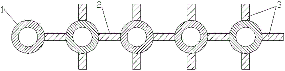
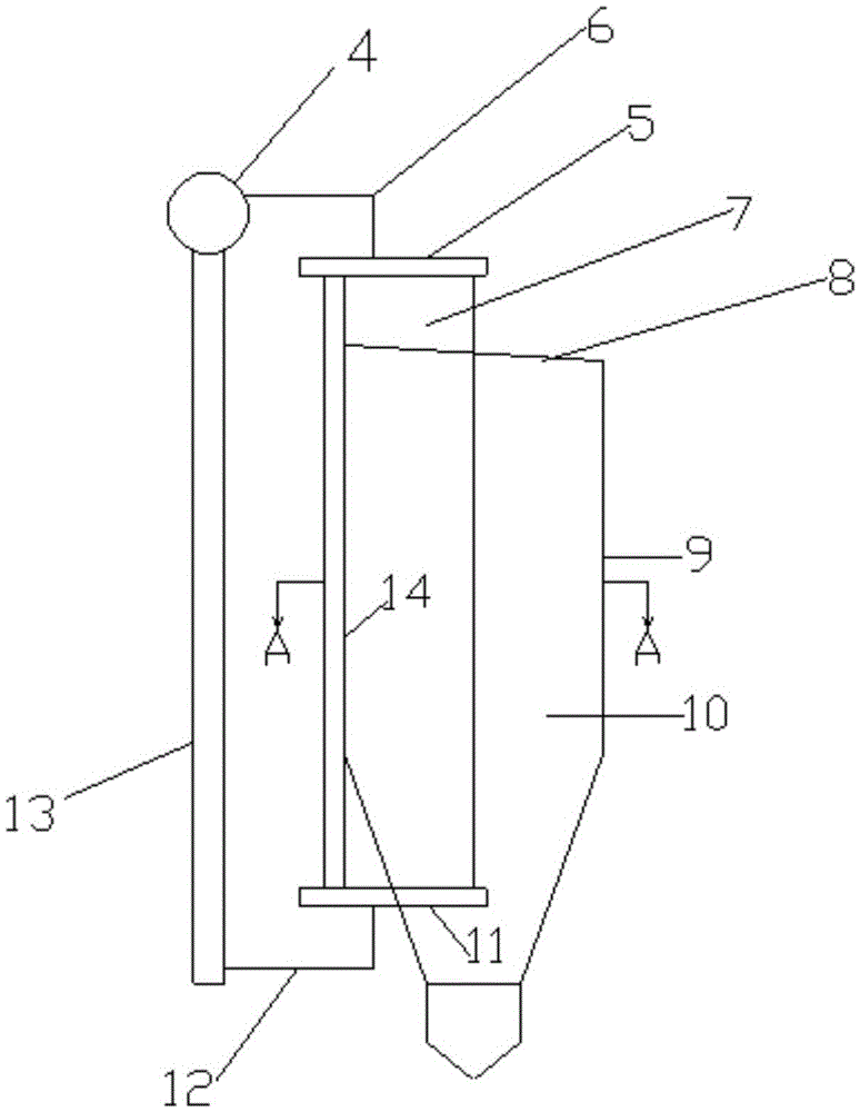
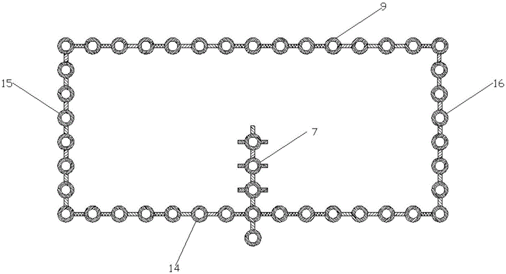
[0014] Such as Figure 1-3 As shown, it is a structural schematic diagram of a large-scale circulating fluidized bed boiler furnace temperature and water cooling control device in an illustrative embodiment.

[0015] In the large-scale circulating fluidized bed boiler furnace temperature water cooling control device in the embodiment, the water circulation system includes a furnace 10 surrounded by a front wall 14, a rear wall 9, a left side wall 15, ...


PUM


Abstract

The invention discloses a hearth temperature water-cooling control device for a large circulating fluidized bed boiler. By the adoption of the hearth temperature water-cooling control device for the large circulating fluidized bed boiler, the problem that the hearth temperature of a circulating fluidized bed boiler is slightly higher and difficult to control is solved. The hearth temperature water-cooling control device for the large circulating fluidized bed boiler comprises a hearth, a water-cooling partition wall, a steam pocket, connecting pipes, an upper header and a lower header, wherein the water-cooling partition wall, the steam pocket, the connecting pipes, the upper header and the lower header are located in the hearth. The hearth comprises a hearth roof, a front wall, a rear wall, a left side wall and a right side wall, wherein a rectangular cylinder is formed by the front wall, the rear wall, the left side wall and the right side wall. The water-cooling partition wall comprises a plurality of heat exchange pipes, abrasion-proof fins and flat steel, wherein the heat exchange pipes are arranged on the same plane in parallel, the flat steel is welded between every two adjacent heat exchange pipes, and the heat exchange pipes and the flat steel are arranged linearly; the abrasion-proof fins are welded to the two sides of each heat exchange pipe. The water-cooling partition wall horizontally extends to the middle of the hearth and vertically penetrates through the hearth. The upper end and the lower end of the water-cooling partition wall communicate with the upper header and the lower header correspondingly. The upper header and the lower header communicate with the steam pocket through the connecting pipes, and a circulation loop is formed. One side of the water-cooling partition wall is fixedly connected to the middle of the front wall of the hearth and is perpendicular to the front wall, and the other side of the water-cooling partition wall horizontally extends to the middle of the hearth.

Description

technical field [0001] The invention relates to the field of circulating fluidized bed boilers, in particular to a large-scale circulating fluidized bed boiler furnace temperature and water cooling control device, which is used to control the bed temperature, reduce the initial generation of pollutants, reduce the input of desulfurization and denitrification agents, and prolong evaporation and heating Surface service life. Background technique [0002] Circulating fluidized bed boilers are widely used because they are suitable for burning high-ash low-quality fuels, low-volatile anthracite, and washed medium coal, coal gangue, coal slime, biomass, garbage, etc., and are developing in the direction of high parameters and large capacity. At the same time as large-scale, the design and operation bed temperature of circulating fluidized bed boilers has an obvious upward trend, reaching 880 ℃ ~ 920 ℃, and even reaching about 960 ℃ for some difficult-to-combustible coal types. Co...

Claims


Application Information

Patent Timeline
Patent Type & Authority Applications(China)
IPC IPC(8): F23C10/28
CPCF23C10/28F23C2206/10
Inventor 柳成亮李东雄郝海俊耿瑞明徐鸿恩
Owner SHANXI GUOFENG COAL POWER CO LTD
Why Eureka
Try Eureka