System for testing friction force and slip characteristics of O-shaped rubber ring in pressurized state

A characteristic test and friction technology, which is applied in the field of friction and slip characteristic test system under the high-pressure O apron pressure state of the gas pressure reducing valve, can solve the problems of high working pressure, pressure deviation at the outlet of the pressure reducing valve, and pressure reduction. Problems such as valve deviation

Active Publication Date: 2020-07-03
SHANGHAI AEROSPACE SYST ENG INST
View PDF6 Cites 0 Cited by
  • Summary
  • Abstract
  • Description
  • Claims
  • Application Information

AI Technical Summary

Problems solved by technology

In the pressure reducing valves used in the existing pressurized delivery system, O rubber rings are used to ensure the isolation between the high pressure chamber of the pressure reducing valve and the feedback chamber. Due to the high working pressure of the gas pressure reducing valve used in the booster delivery system of the launch vehicle, resulting in high pressure O Under the action of the pressure on both sides of the high-pressure chamber and the feedback chamber, the pressure friction of the apron is far greater than that of the non-pressure state, which makes the pressure reducing valve deviate from the design working point, resulting in pressure deviation and out-of-tolerance at the outlet of the pressure reducing valve.

Method used


Image

  • System for testing friction force and slip characteristics of O-shaped rubber ring in pressurized state
  • System for testing friction force and slip characteristics of O-shaped rubber ring in pressurized state

Examples


Embodiment Construction

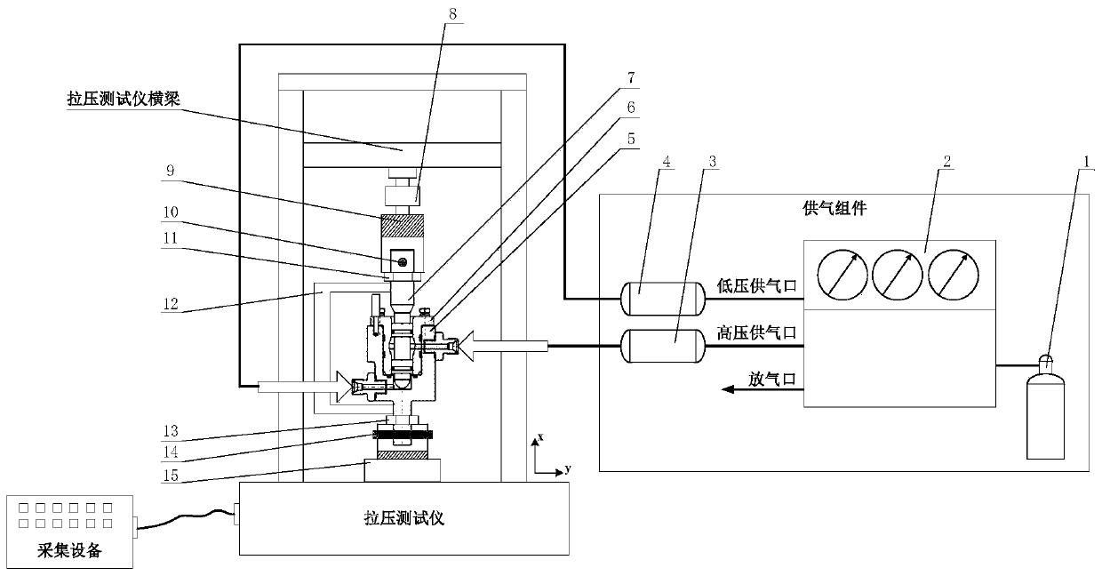
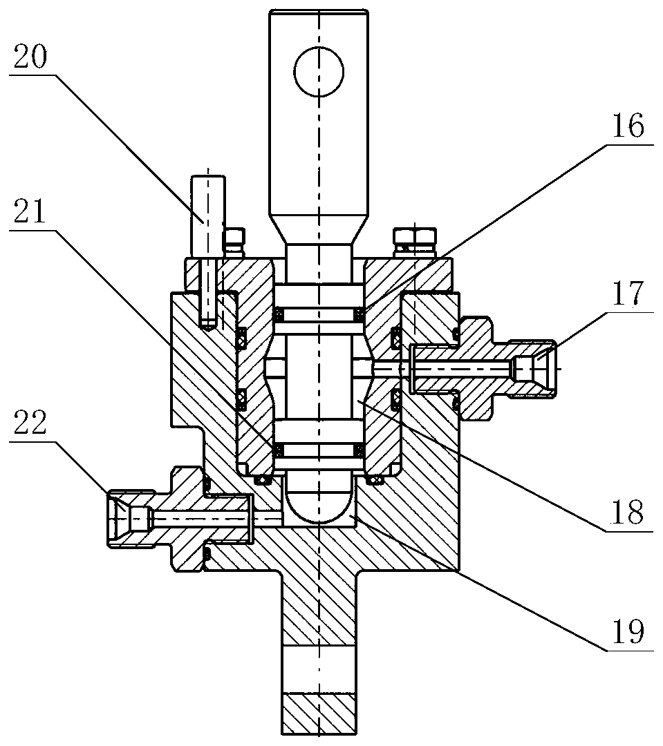
[0026] The following will combine Figure 1 ~ Figure 2 A further detailed description is made on the test system for the friction and slip characteristics of an O rubber ring in a pressurized state of the present invention.

[0027] figure 1 , figure 2 Shown is a schematic diagram of a test system for friction and slip characteristics of an O rubber ring in a pressurized state of the present invention. The system includes: an air supply assembly, a tooling shell base 5, a tooling shell 6, a tooling valve core 7, Force sensor 8, first clamp 9, first connecting pin 10, first lock nut 11, displacement sensor 12, second lock nut 13, second connecting pin 14, second clamp 15, first O glue Ring 16, first nozzle 17, first air chamber 18, second air chamber 19, positioning pin 20, second O rubber ring 21, second nozzle 22, tension and pressure tester, collection equipment; among them, air supply The assembly further includes: a gas cylinder 1 , a gas distribution platform 2 , a fi...


PUM


Abstract

The invention relates to a system for testing friction force and slip characteristics of an O-shaped rubber ring in a pressurized state. Stable gas pressures with different pressures are respectivelysupplied to the two sides of the O-shaped rubber ring through the gas supply assembly at the same time. The tool valve element is driven to move relative to the tool shell and the tool shell base through the first clamp and the first connecting pin of the tension and compression tester. By arranging a first buffer container and a second buffer container, the pressure change caused by heat exchangeand tool valve element movement after the two sides of the O-shaped rubber ring are pressurized is reduced, and the friction force of the O-shaped rubber ring under various different working conditions is measured through the force sensor, the displacement sensor and the collecting equipment. According to the invention, stable gas pressures with different pressures can be supplied to the two sides of the O-shaped rubber ring simultaneously and respectively. The pressure and differential pressure boundary conditions of the O-shaped rubber ring in the working process of the gas pressure reducing valve are truly simulated, the friction force of the O-shaped rubber ring under different sliding boundary conditions is accurately measured, and data support is provided for performance design andprecision improvement of the gas pressure reducing valve.

Description

technical field [0001] The invention relates to a test system for friction force and slip characteristics under the state of O-apron pressure filling, in particular to a gas decompression valve for a booster delivery system of a carrier rocket under high-pressure O-apron pressure state and friction force and slippage Characteristic test system. Background technique [0002] The gas pressure reducing valve is an important stand-alone unit used in the pressurized delivery system of the launch vehicle. Its function is to decompress the high-pressure gas stored in the cylinder and stabilize the pressure within a certain range to pressurize the propellant tank. In the pressure reducing valves used in the existing pressurized delivery system, O rubber rings are used to ensure the isolation between the high pressure chamber of the pressure reducing valve and the feedback chamber. Due to the high working pressure of the gas pressure reducing valve used in the booster delivery system...

Claims


Application Information

Patent Timeline
Patent Type & Authority Applications(China)
IPC IPC(8): G01M13/005G01N19/02G01L5/00
CPCG01M13/005G01N19/02G01L5/0028
Inventor 张明臧辉郭志海白沐炎石玉鹏徐笠云
Owner SHANGHAI AEROSPACE SYST ENG INST
Why Eureka
Try Eureka