Automatic optical detection method

A technology for automatic optical inspection and the object under test, which is applied in the field of optical inspection, can solve the problems of increased maintenance cost, difficult cooperation, negative production efficiency and product yield rate, etc., so as to improve production efficiency, reduce maintenance cost, and maintain product quality. rate effect

Inactive Publication Date: 2020-07-03
广东吉洋视觉技术有限公司
View PDF3 Cites 0 Cited by
  • Summary
  • Abstract
  • Description
  • Claims
  • Application Information

AI Technical Summary

Problems solved by technology

[0003] However, sometimes in order to respond to different product requirements, a variety of different image collectors (such as CCD, CMOS or Webcam) or multiple control systems may be configured on the production site, but there are often system differences between these different image collectors. Compatibility issues, in addition to easily causing trouble for maintenance personnel and increasing maintenance costs, it is also difficult to work together to form a consistent production process, which will inevitably have a negative impact on production efficiency and product yield.

Method used


Image

  • Automatic optical detection method

Examples


Embodiment Construction

[0017] Below in conjunction with accompanying drawing and embodiment the present invention will be further described:

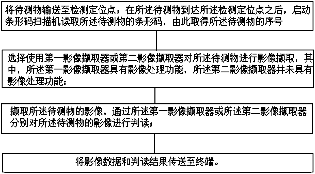
[0018] like figure 1 As shown, the embodiment of the present invention discloses an automatic optical detection method, which includes the following steps:

[0019] 1) Transport the object to be tested to the detection location point; after the object to be tested reaches the detection location point, start the barcode scanner to read the barcode of the object to be tested, thereby obtaining the serial number of the object to be tested ;

[0020] 2) Choose to use the first image collector or the second image collector to collect the image of the object under test, wherein the first image collector has an image processing function, and the second image collector does not have an image processing function;

[0021] 3) collecting images of the object to be measured, and interpreting the images of the object to be measured through the first image collector or ...


PUM


Abstract

The invention discloses an automatic optical detection method. The method comprises the following steps: conveying a to-be-detected object to a detection positioning point; after the to-be-detected object reaches the detection positioning point, starting a bar code scanner to read a bar code of the to-be-detected object so as to obtain a serial number of the to-be-detected object; selecting a first image collector or a second image collector to collect the image of the to-be-detected object, wherein the first image collector has an image processing function, and the second image collector doesnot have the image processing function; collecting the image of the to-be-detected object, and interpreting the image of the to-be-detected object through the first image collector or the second image collector; and transmitting the image data and the interpretation result to a terminal. Through the automatic optical detection method provided by the invention, the production efficiency is improved.

Description

technical field [0001] The invention relates to the field of optical detection, in particular to an automatic optical detection method. Background technique [0002] As far as Automatic Optical Inspection (AOI) is concerned, the traditional inspection step is to first use the conveyor belt to transport the object to be tested (such as a circuit board) to the inspection positioning point, and then pass through the image collector set at the detection positioning point. After collecting the image of the object to be tested, the collected image data is sent to the computer, and the operator performs subsequent image storage and defect interpretation. [0003] However, sometimes in order to respond to different product requirements, a variety of different image collectors (such as CCD, CMOS or Webcam) or multiple sets of control systems may be configured on the production site, but there are often system differences between these different image collectors. Compatibility issues...

Claims


Application Information

Patent Timeline
IPC IPC(8): G01N21/84G01N21/88G01N21/01
CPCG01N21/84G01N21/88G01N21/8851G01N21/01G01N2021/845G01N2021/0112
Inventor 黄采敏
Owner 广东吉洋视觉技术有限公司
Why Eureka
Try Eureka