
Device and method for optical axis correction of optical lens

An optical lens and correction device technology, applied in optics, optical components, instruments, etc., can solve the problems of low mirror alignment accuracy, long time required for lens alignment, and high alignment cost, and achieve easy operation, simple and uncomplicated algorithms. , the effect of less error

Active Publication Date: 2020-09-01
宁波丞达精机股份有限公司
View PDF5 Cites 0 Cited by
  • Summary
  • Abstract
  • Description
  • Claims
  • Application Information

AI Technical Summary

Problems solved by technology

[0003] The problem to be solved by the present invention is to provide a device and method for correcting the optical axis of an optical lens, which solves the problems of long time required for alignment of the existing lens, high alignment cost and low alignment accuracy, and can realize rapid optical correction. The optical axis of the lens, for the purpose of improving its correction accuracy

Method used


Image

  • Device and method for optical axis correction of optical lens
  • Device and method for optical axis correction of optical lens
  • Device and method for optical axis correction of optical lens

Examples


Embodiment Construction

[0031] The specific implementation manners of the present invention will be further described in detail below in conjunction with the accompanying drawings and embodiments. The following examples are used to illustrate the present invention, but are not intended to limit the scope of the present invention.

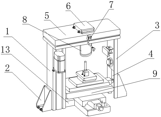
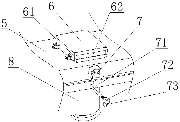
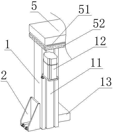
[0032] refer to Figure 1-5 , the technical solution provided by the present invention is: an optical lens optical axis correction device, comprising a frame one 1, a frame two 3, a top seat 5, an imaging assembly 6 and a moving device 9, and the top of the frame one 1 is provided with a top seat 5. The bottom of the right end of the top seat 5 is provided with a frame two 3, the left side of the frame two 3 is provided with a lighting adjustment plate 31, the bottom of the outer end of the frame one 1 and frame two 3 is respectively provided with a fixed card seat 2, and the top seat 5 is provided with an imaging assembly 6 in the center, an alignment correction assembly...


PUM


Abstract

The invention relates to the field of optical lens processing, and particularly discloses an optical lens optical axis correction device and method. The optical lens optical axis correction device comprises a rack I, a rack II, a top seat, an imaging assembly and a moving device, wherein the top seat is arranged at the top end of the rack I, the rack II is arranged at the bottom of the right end of the top seat, the imaging assembly is arranged in the center of the top seat, an alignment correction assembly is arranged at the front end of the top seat, an imaging channel is formed in the bottom end of the imaging assembly, and the moving device is arranged below the imaging channel. According to the invention, under the premise that the optical lens coincides with the optical axis of a film image, the optical axis offset condition of the optical lens is analyzed through an image which is shot by the lens for the perpendicular incidence generated by the film image; and the moving deviceis controlled to rapidly adjust the moving range according to the correction parameters, and the alignment process is adjusted in time through an adjusting mechanism, so that errors are not likely tobe caused, the optical axis alignment efficiency and precision of a miniature optical lens are greatly improved, and the cost is saved.

Description

technical field [0001] The invention relates to the technical processing field of lens correction equipment, in particular to an optical lens optical axis correction device and method. Background technique [0002] The traditional optical axis correction device cannot adjust the deflection angles in the horizontal, vertical, and vertical directions at the same time. When adjusting each other, it is difficult to quickly adjust the optical path. Existing handheld mobile devices such as mobile phones and tablet computers are becoming more and more popular, and people also have high requirements for the shooting functions of these devices. Therefore, there is a large demand for micro-lenses and high requirements for production capacity. The alignment of the optical axis of the micro-optical lens is an important step in the assembly of the camera components of the mobile device. The traditional method of aligning the micro-optical lens is mostly to use a mechanical method to adju...

Claims


Application Information

Patent Timeline
Patent Type & Authority Patents(China)
IPC IPC(8): G02B27/62
CPCG02B27/62
Inventor 付丞
Owner 宁波丞达精机股份有限公司
Learn More