Electronic device

A technology for electronic devices and electronic components, which can be used in electrical digital data processing, digital processing power distribution, instruments, etc., and can solve problems such as affecting the heat dissipation efficiency of electronic components.

Active Publication Date: 2020-07-03
HONG FU JIN PRECISION IND WUHAN CO LTD +1
View PDF8 Cites 0 Cited by
  • Summary
  • Abstract
  • Description
  • Claims
  • Application Information

AI Technical Summary

Problems solved by technology

Although the above-mentioned air flow can drive heat to the outside of the chassis, because the air flow passes through one set of electronic components, such as a CPU or a set of memory sticks, before flowing to another set of electronic components, such as another CPU or another set of memory sticks, Therefore, when the air flow reaches another group of electronic components, it has already carried a certain amount of heat, and there is a risk that the heat generated by the other group of electronic components cannot be carried out of the chassis through the air flow, thereby affecting the heat dissipation efficiency of the electronic components

Method used


Image

  • Electronic device
  • Electronic device
  • Electronic device

Examples


Embodiment Construction

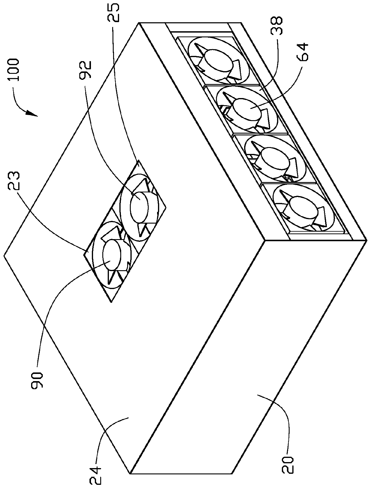
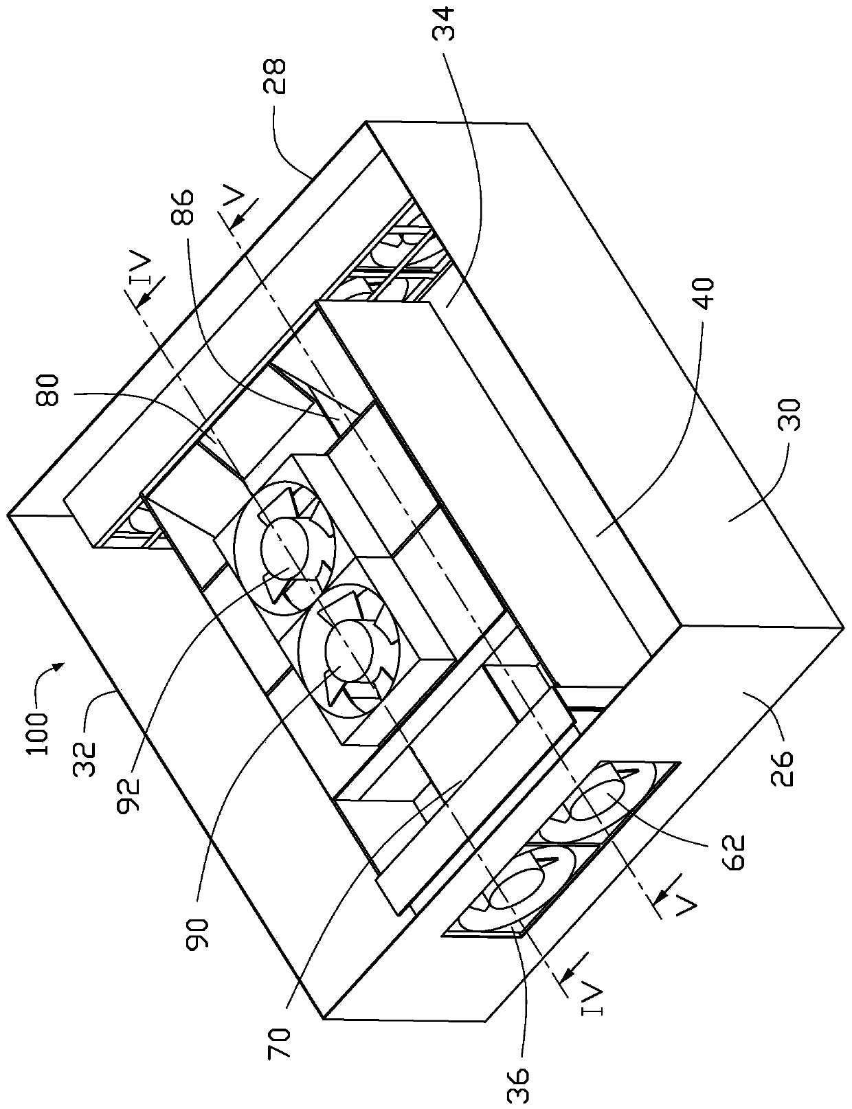
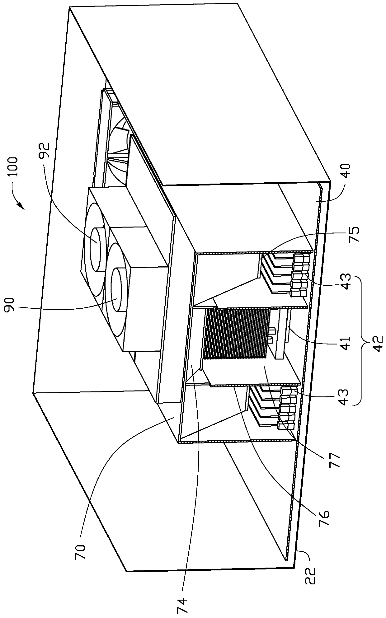
[0061] see Figure 1 to Figure 5 , an electronic device 100 includes a box body 20 and a motherboard 40 fixed in the box body 20 . The box body 20 includes a bottom shell 22 , a top shell 24 , a first side shell 26 , a second side shell 28 , a third side shell 30 and a fourth side shell 32 . The first side shell 26 , the third side shell 30 , the second side shell 28 and the fourth side shell 32 are connected end-to-end and fixed between the bottom shell 22 and the top shell 24 . The bottom shell 22 , the top shell 24 , the first side shell 26 , the second side shell 28 , the third side shell 30 and the fourth side shell 32 form a receiving space 34 . In this embodiment, the first side shell 26 is arranged parallel to the second side shell 28 , and the third side shell 30 is arranged parallel to the fourth side shell 32 . The first side shell 26 is formed with several first air inlets 36 . Several second air inlets 38 are formed on the second side shell 28 . The top case 2...


PUM


Abstract

An electronic device comprises a box body, a mainboard, a first group of electronic components, a second group of electronic components, a first air guide cover, a second air guide cover, a partitionplate, a first air suction fan, a second air suction fan, a first air blowing fan and a second air blowing fan. The box body comprises a bottom shell, a top shell, a first side shell and a second sideshell. A first air inlet and a second air inlet are respectively formed in the first side shell and the second side shell; a first air outlet hole and a second air outlet hole are formed in the top shell; the first group of electronic elements and the second group of electronic elements are isolated by the clapboard; the first wind scooper guides air sucked to the box body by the first air suction fan through the first air inlet to the first group of electronic elements; the first blowing fan blows air guided to the first group of electronic components out of the box body through the first air outlet holes; the second wind scooper guides the air sucked to the box body by the second air suction fan through the second air inlet to the second group of electronic elements, and the second blowing fan blows the air guided to the second group of electronic elements out of the box body through the second air outlet hole.

Description

technical field [0001] The present invention relates to electronic devices. Background technique [0002] In order to enhance the processing performance of the electronic device, the main board in the case of the electronic device is generally provided with multiple sets of electronic components, such as multiple CPUs and multiple sets of memory sticks. Multiple sets of electronic components are usually arranged in series on the motherboard. In order to drive the heat generated by the electronic components to the outside of the chassis, ventilation holes are usually provided on the two opposite casings of the chassis in the serial direction of the electronic components, and the fan is placed at the ventilation hole, and the ventilation hole from one casing is formed by the operation of the fan. The airflow that enters and blows out from the ventilation holes of the other casing blows the heat generated by the electronic components to the outside of the casing. Although the...

Claims


Application Information

Patent Timeline
Patent Type & Authority Applications(China)
IPC IPC(8): G06F1/18G06F1/20
CPCG06F1/182G06F1/183G06F1/20
Inventor 谢宜莳罗鹏
Owner HONG FU JIN PRECISION IND WUHAN CO LTD
Why Eureka
Try Eureka