Repositioning method and terminal equipment

A relocation and image technology, applied in the computer field, can solve problems such as wrong matching and positioning errors, and achieve the effect of accurate matching and improved positioning accuracy

Pending Publication Date: 2020-07-03
UBTECH ROBOTICS CORP LTD
View PDF5 Cites 4 Cited by
  • Summary
  • Abstract
  • Description
  • Claims
  • Application Information

AI Technical Summary

Problems solved by technology

[0004] In view of this, the embodiment of the present invention provides a relocation method and a terminal device to solve the problem that when the current scene and the image scene used for model training are quite different from the current relocation method based on vision, it is easy to cause a wrong match and a wrong positioning. question

Method used


Image

  • Repositioning method and terminal equipment
  • Repositioning method and terminal equipment
  • Repositioning method and terminal equipment

Examples


Embodiment Construction

[0027] In the following description, specific details such as specific system structures and technologies are presented for the purpose of illustration rather than limitation, so as to thoroughly understand the embodiments of the present invention. It will be apparent, however, to one skilled in the art that the invention may be practiced in other embodiments without these specific details. In other instances, detailed descriptions of well-known systems, devices, circuits, and methods are omitted so as not to obscure the description of the present invention with unnecessary detail.

[0028] In order to illustrate the technical solutions of the present invention, specific examples are used below to illustrate.

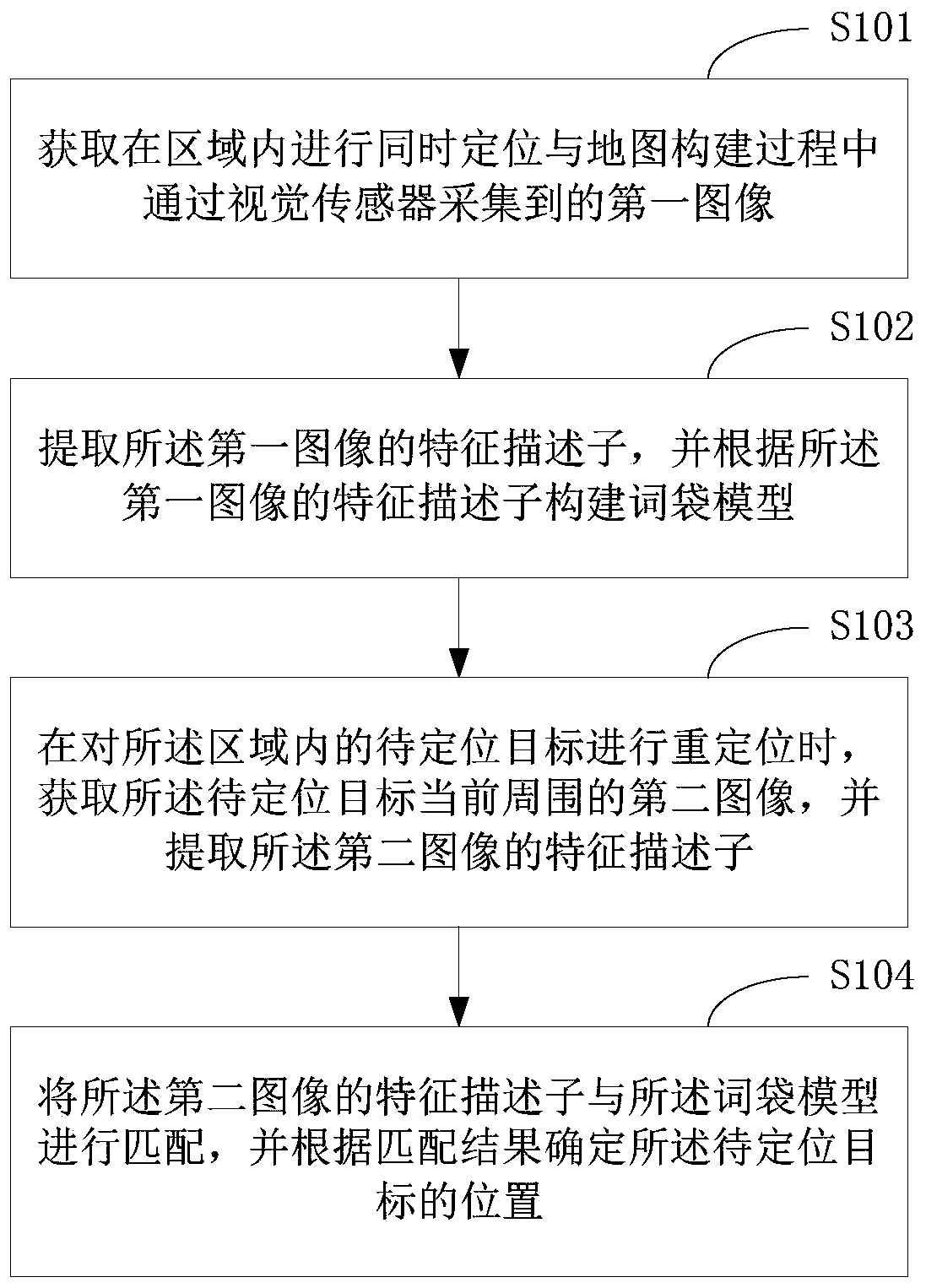
[0029] figure 1 The implementation flowchart of the relocation method provided by the embodiment of the present invention is described in detail as follows:

[0030] S101. Acquire a first image collected by a visual sensor during simultaneous positioning and map build...


PUM


Abstract

The invention relates to the technical field of computers, and provides a repositioning method and terminal equipment. The method comprises the following steps: acquiring a first image acquired by a visual sensor in a process of carrying out simultaneous localization and map construction in a region; extracting a feature descriptor of the first image, and constructing a bag-of-words model according to the feature descriptor of the first image; when a to-be-positioned target in the area is repositioned, a second image around the to-be-positioned target at present is acquired, and a feature descriptor of the second image is extracted; and matching the feature descriptor of the second image with the bag-of-words model, and determining the position of the to-be-positioned target according to amatching result. According to the invention, the matching of the image around the to-be-positioned target and the bag-of-words model in the repositioning process is more accurate, and the positioningaccuracy is further improved.

Description

technical field [0001] The present invention relates to the field of computer technology, in particular to a relocation method and terminal equipment. Background technique [0002] At present, most of the relatively mature positioning and navigation solutions for indoor service robots are based on laser SLAM (Simultaneous Localization And Mapping, simultaneous positioning and map construction) technology, because the laser SLAM solution is superior to the visual SLAM solution in terms of positioning accuracy and robustness. However, laser SLAM still cannot solve the relocation problem well in large scenes. Based on the above background, other sensors are needed to help the robot relocate. The added sensors must not be too expensive, the generated map must not be too large, and the relocation must be fast and accurate. The vision sensor basically satisfies these points. [0003] The more mature scheme of the traditional vision-based relocation method is the DBOW2 method, w...

Claims


Application Information

Patent Timeline
Patent Type & Authority Applications(China)
IPC IPC(8): G06K9/62
CPCG06V10/751
Inventor 熊友军蒋晨晨毕占甲张健庞建新
Owner UBTECH ROBOTICS CORP LTD
Why Eureka
Try Eureka