Precise parking method, device and system for truck in shore crane area

A truck and precise technology, applied in the field of intelligent transportation, can solve problems such as slow speed, unsuitable for large trucks to accurately park, and large errors

Active Publication Date: 2020-07-03
BEIJING TUSEN ZHITU TECH CO LTD
View PDF12 Cites 8 Cited by
  • Summary
  • Abstract
  • Description
  • Claims
  • Application Information

AI Technical Summary

Problems solved by technology

[0003] At present, the most common vehicle parking methods are to locate vehicles and parking spaces through vehicle positioning equipment or vehic

Method used


Image

  • Precise parking method, device and system for truck in shore crane area
  • Precise parking method, device and system for truck in shore crane area
  • Precise parking method, device and system for truck in shore crane area

Examples


Embodiment 1

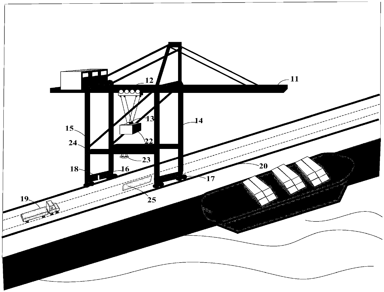
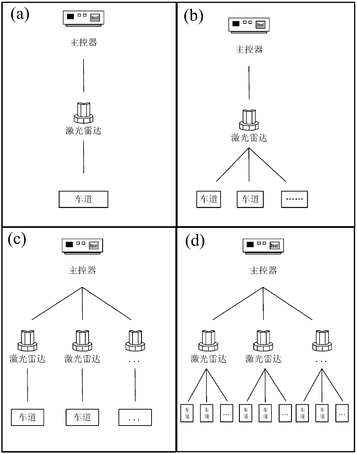
[0144] Such as Figure 5 As shown, the quay crane numbered AD1000 spans 6 lanes numbered E1~E6, and the bottom of the contact beam of the quay crane is equipped with 6 laser radars numbered Lidar1~Lidar6, and Lidar1~Lidar6 scan E1~Lidar6 respectively. E6, that is, each laser radar is responsible for scanning a lane, and the main controller M is connected to the laser radars Lidar1~Lidar6, and is responsible for the precise parking of trucks on each lane under the shore crane AD1000.

[0145] The main controller M locally stores the following information:

[0146] (1) Lidar numbers Lidar1~Lidar6;

[0147] (2) Shore crane number AD1000;

[0148] (3) Lane numbers E1~E6;

[0149] (4) The first model library and the second model library, wherein the vehicle point cloud model in the first model library corresponds to the truck loaded with containers, and the vehicle point cloud model in the second model library corresponds to the truck without container , the vehicle model of th...

Embodiment 2

[0164] Such as Image 6 As shown, the quay crane numbered AD1000 spans 6 lanes numbered E1~E6 respectively. Two laser radars numbered Lidar1 and Lidar2 are installed at the bottom of the contact beam of the quay crane. Lidar1 is responsible for scanning the lanes E1~E3 , Lidar2 is responsible for scanning E4~E6, that is, each lidar is responsible for scanning 3 lanes, and the main controller M is connected to lidar Lidar1 and Lidar2, and is responsible for the precise parking of trucks on each lane under the shore crane AD1000.

[0165] The main controller M locally stores the following information:

[0166] (1) Lidar numbers Lidar1, Lidar2;

[0167] (2) Shore crane number AD1000;

[0168] (3) Lane numbers E1~E6;

[0169] (4) The first model library and the second model library, wherein the vehicle point cloud model in the first model library corresponds to the truck loaded with containers, and the vehicle point cloud model in the second model library corresponds to the tru...


PUM


Abstract

The embodiment of the invention provides a precise parking method, device and system for a truck in a shore crane area. The accurate parking method for the truck in the shore crane area comprises thefollowing steps: receiving a parking request, sent by a vehicle controller, of a to-be-parked truck; acquiring real-time point cloud data obtained by scanning a lane spanned by the shore crane by a laser radar; clustering the real-time point cloud data to obtain a point cloud set of the to-be-parked truck; utilizing an ICP algorithm to calculate the point cloud set of the to-be-parked truck and avehicle point cloud model, and obtaining and sending a real-time distance from the to-be-parked truck to a target parking space, wherein the vehicle point cloud model is a point cloud set obtained byscanning a truck parked in the target parking space by using the laser radar in advance. The ICP algorithm is used for calculating the real-time distance from the truck to the target parking space, the truck is controlled to accurately stop at the target parking space at a time according to the real-time distance, the whole parking process is automatically completed, manual command is not needed,the centimeter-level precision can be achieved, and the implementation cost is low.

Description

technical field [0001] The embodiments of the present application relate to the technical field of intelligent transportation, and more specifically, the embodiments of the present application relate to a method, equipment and system for precise parking of trucks in a shore crane area. Background technique [0002] This section is intended to provide a background or context to the implementations of the application that are recited in the claims. The descriptions herein are not admitted to be prior art by inclusion in this section. [0003] At present, the common vehicle parking methods are mostly to locate vehicles and parking spaces through vehicle-mounted positioning equipment or vehicle-mounted cameras. This method has disadvantages such as large errors and slow speeds, and is especially not suitable for precise parking of large trucks. [0004] Shoreside container cranes, also known as quayside cranes, are special cranes for loading and unloading containers at port ter...

Claims


Application Information

Patent Timeline
IPC IPC(8): G08G1/00B60W30/06B60W10/18B60W10/06G05D1/02
CPCG08G1/205B60W30/06B60W10/18B60W10/06G05D1/0242G05D1/0253B60W2710/0605B60W2710/18G05D1/0282G05D2201/0205G08G1/143G08G1/207B60W2556/45B60W2300/16B60W2300/125G06V2201/08B62D15/0285G06V20/64G06F18/23Y02T10/40G06T7/521G01S17/931G06V10/751B60W10/04B60W50/0098B60W2050/006B60W2300/12B60W2420/52B66C13/18B66C19/002G01S7/4802G01S17/42G06T2207/10028G06F18/232
Inventor 李一鸣肖旭金宇和蔡金鹏吴楠
Owner BEIJING TUSEN ZHITU TECH CO LTD
Why Eureka
Try Eureka