
Terminal crimping die with material pressing mechanism

A terminal crimping and mold technology, applied in connection, electrical components, circuits, etc., can solve problems such as damage, waste of terminals, inaccurate feeding of terminal strips, etc.

Pending Publication Date: 2020-07-03
CYUANHUA(FUJIAN) ELECTRIC TECHNOLOGY CO.,LTD.
View PDF1 Cites 4 Cited by
  • Summary
  • Abstract
  • Description
  • Claims
  • Application Information

AI Technical Summary

Problems solved by technology

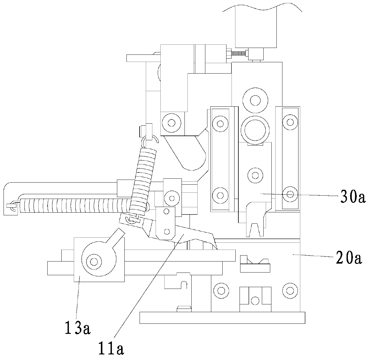
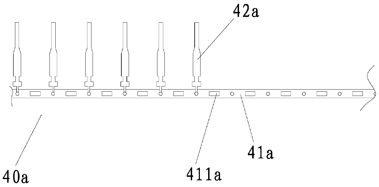
[0005] However, the feeding mechanism is located on the rear side of the mold base 20a, resulting in the support plate 13a being unable to press the terminal material when the last section of the terminal strip is delivered (that is, the last section of each terminal strip has about 4-16 terminals). At this time, the terminal strip is in a loose state, and because the feeding claw 11a will move backward when the upper die 30a of the crimping machine is punched downward, the feeding claw 11a will drive the terminal strip to move backward, so that it is impossible to press the terminal strip. Terminals on the last section of strip are crimped, resulting in wasted terminals
Moreover, calculated according to the output of the factory, the annual consumption of terminals is about 40 million, and the waste of terminal materials is about 60,000, which causes a lot of waste. At the same time, the entire terminal strip is crimped to In the last period, the pressing plate 13a cannot press the terminal strip, so the terminal strip is not fed correctly, and it is easy to damage the lower die of the crimping machine due to air pressure when it is punched downward.

Method used


Image

  • Terminal crimping die with material pressing mechanism
  • Terminal crimping die with material pressing mechanism
  • Terminal crimping die with material pressing mechanism

Examples


Embodiment Construction

[0042] In order to further explain the technical solution of the present invention, the present invention will be described in detail below through specific examples.

[0043] A terminal crimping die with a pressing mechanism is improved on the basis of the existing terminal crimping die.

[0044] For the convenience of description, the orientation of the terminal crimping mold in normal use is taken as the reference direction, and the side of the user facing the terminal crimping mold is the left side, and the side away from it is the right side.

[0045] like Figure 1-2 As shown, the existing terminal crimping mold also includes a mold base 20a, an upper mold 30a and the above-mentioned feeding mechanism. Upper mold 30a is installed on the mold base 20a in the mode that can lift up and down, and the installation structure of upper mold 30a is existing conventional installation structure, referring to the installation structure of upper mold in the existing crimping mold on ...


PUM


Abstract

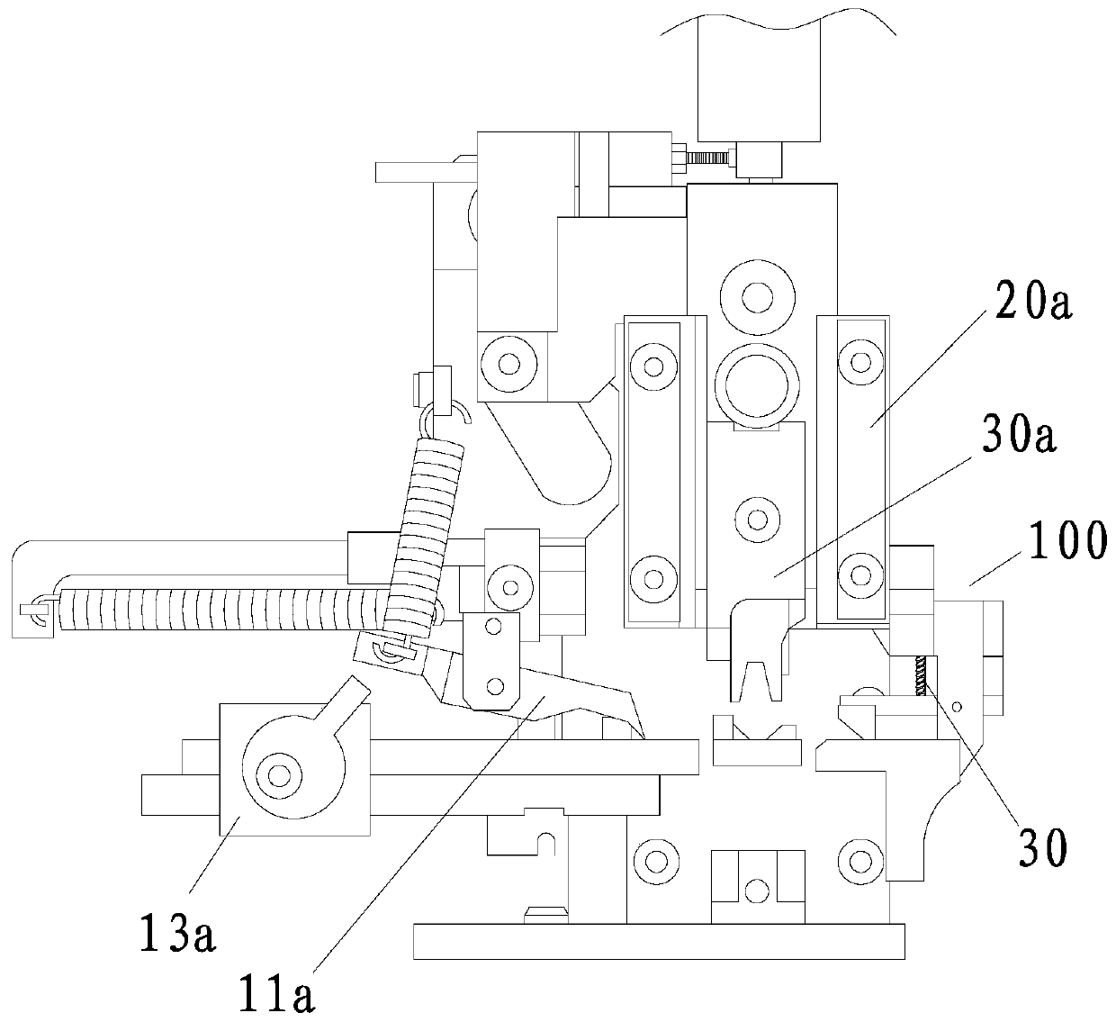
The invention discloses a terminal crimping die with a material pressing mechanism. The die comprises a material pressing mechanism. The material pressing mechanism comprises a seat body and a pressing claw used for extending into a process hole of a terminal material belt. The pressing claw is mounted on the seat body in a manner of swinging up and down. A telescopic spring is arranged between the seat body and the pressing claw. A conveying part is arranged on the seat body. The conveying part is located in the conveying direction of the terminal material belt, and an abutting part is arranged at one end of the pressing claw from back to front with the conveying direction of the terminal material belt as the conveying direction. The abutting part comprises an inclined section and a straight section located on the front side of the inclined section. The inclined section and the first end of the straight section are connected to form a tip, and the tip abuts against the conveying part.Compared with the prior art, when the material pressing plate cannot press the terminal material belt, the terminal material belt is positioned through the pressing claws, so that the terminal material belt is always in a crimping state, terminals in the whole disc of terminal material belt are effectively utilized, the utilization rate of the terminals in the terminal material belt is improved,and resource waste is avoided.

Description

technical field [0001] The invention relates to a terminal crimping die, in particular to a terminal crimping die with a pressing mechanism. Background technique [0002] The production of automotive wiring harness usually includes stripping process, crimping process and final assembly process. Among them, the crimping process is an important part of the wire harness production. It is a process of using a crimping machine to squeeze and deform the terminal to firmly connect the terminal to the wire. [0003] The crimping machine includes terminal crimping dies. There are many types of terminal crimping dies. The terminal crimping dies commonly used in factories are European crimping dies, Japanese crimping dies and the applicant's application for "a terminal with a protective device". crimping die", the feeding method of these terminal crimping dies is to use the feeding mechanism to transport the terminal strip. [0004] like Figure 1-2 As shown, the conveying direction ...

Claims


Application Information

Patent Timeline
IPC IPC(8): H01R43/048H01R43/055
CPCH01R43/048H01R43/055
Inventor 萧森荣
Owner CYUANHUA(FUJIAN) ELECTRIC TECHNOLOGY CO.,LTD.
Learn More