Up-flow reactor and application thereof

A reactor and upflow technology, applied in chemical instruments and methods, petroleum industry, hydrocarbon oil treatment, etc., can solve problems such as clogging, clogging distributor, uneven distribution of fluid gas, etc.

Active Publication Date: 2020-07-07
CHINA PETROLEUM & CHEM CORP +1
View PDF13 Cites 2 Cited by
  • Summary
  • Abstract
  • Description
  • Claims
  • Application Information

AI Technical Summary

Problems solved by technology

Since the catalyst particles cannot pass through the small bed support gap, these particles are likely to block the distributor or bed support, resulting in uneven distribution of fluid, especially gas, which affects the distribution of fluid in the reactor and affects the reaction process. adversely affect
At the same time, i...

Method used


Image

  • Up-flow reactor and application thereof
  • Up-flow reactor and application thereof
  • Up-flow reactor and application thereof

Examples


Embodiment 1

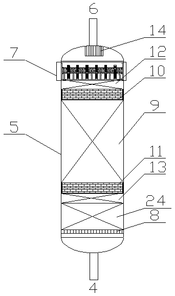
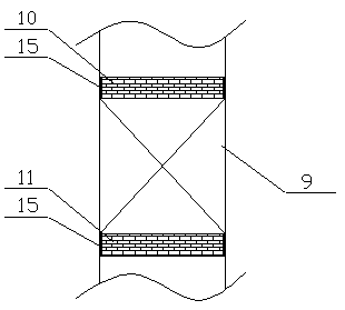
[0044] Using the upflow reactor described in the present invention, the raw material oil and hydrogen are mixed using a conventional static mixer (model SX2.3 / 20-6.4-450), and then the mixture is introduced into the present invention as a reactor feed Upflow reactor (reactor diameter is 100mm), the reactor is filled with catalyst bed supporting grid, protective agent layer 100mm, second ceramic ball supporting layer 60mm, second plastic elastomer bed in sequence along the material flow direction Layer 50mm, catalyst bed 550mm (12-mesh stainless steel wire mesh is laid on top of the catalyst bed), ceramic ball layer 100mm; the catalyst bed support grid is spliced ​​by parallel metal grid strips, and the upper surface of the grid is screened Tiled 20-mesh screen; the second ceramic ball supporting layer is filled with φ20mm inert ceramic balls, and the outside is surrounded by an integrated frame structure made of wire mesh with a wire diameter of 1mm; the second plastic elastome...

Embodiment 2

[0046] Using the upflow reactor of the present invention, the raw material oil and hydrogen are mixed with an inorganic membrane tube disperser. First, the hydrogen is dispersed into microbubbles with a size of 50nm and then penetrates out of the tube to form a reaction with the liquid introduced into the shell. The reactor feed mixture is then introduced into the upflow reactor of the present invention as the reactor feed (the diameter of the upflow reactor is 200 mm); the catalyst bed support grid is filled in the upflow reactor along the direction of material flow , protective agent layer 50mm, catalyst bed layer 600mm, first plastic elastomer bed layer 30mm, first ceramic ball supporting layer 50mm, floating ash removal layer 100mm (the fixed height of the ash filter layer is 50mm, and the internal filling of the fixed interlayer It is made of φ13mm alumina ceramic balls; the filter cartridge shell is made of Johnson mesh, filled with φ3-φ6mm alumina ceramic balls; the tota...

Embodiment 3

[0048] Using the upflow reactor described in the present invention, the raw material oil and hydrogen are mixed using a conventional static mixer (model SX2.3 / 20-6.4-450), and then the mixture is introduced into the present invention as a reactor feed The upflow reactor (reactor diameter is 200mm); the upflow reactor is sequentially filled with catalyst bed support grid, second ceramic ball support layer 30mm, second plastic elastomer bed 80mm, The catalyst bed is 550mm, the first plastic elastomer bed is 80mm, the first ceramic ball supporting layer is 30mm, and the floating ash removal layer is 150mm (the fixed height of the ash filter layer is 75mm, and the fixed interlayer is filled with φ13mm alumina ceramic balls ;The shell of the filter cartridge is made of Johnson mesh, filled with φ3-φ6mm alumina ceramic balls); the total length of the slideway is 180mm; the catalyst bed support grid is spliced ​​by parallel metal grid bars, and the upper surface of the grid is sieved ...


PUM


Abstract

The invention discloses an up-flow reactor and application thereof; the up-flow reactor comprises a reactor shell; a catalyst bed layer supporting grid and a catalyst bed layer are sequentially arranged in the reactor shell in the material flowing direction; an elastic supporting layer is arranged at the lower part of the catalyst bed layer and/or the upper part of the catalyst bed layer; the elastic supporting layer comprises a plastic elastomer bed layer and a ceramic ball supporting layer, the plastic elastomer bed layer comprises a plurality of plastic elastomer units, the plastic elastomer units internally comprise particles prepared from an elastic material, and gaps are formed between the plastic elastomer units and in the plastic elastomer units to serve as channels for fluid to flow through. The invention also provides an application of the up-flow reactor. The plastic elastomer bed layer in the up-flow reactor can deform synchronously along with expansion and contraction of the catalyst bed layer, bed layer pressure drop increase caused by particle abrasion in the floating process of a catalyst is prevented, and long-period stable operation of the up-flow reactor is guaranteed.

Description

technical field [0001] The invention belongs to the field of petrochemical equipment, and relates to an upflow reactor and its application. Background technique [0002] In the field of petrochemical industry, hydrogenation process is an important technical means for processing distillate oil and secondary processed oil. Through hydrogenation, impurities such as sulfur, nitrogen, metals, colloids, and residual carbon in oil products can be effectively removed. Removal and hydrogenation of unsaturated hydrocarbons to saturated hydrocarbons. According to the type of reactor, the hydrogenation process can be divided into fixed bed hydrogenation process, suspension bed hydrogenation process and ebullated bed hydrogenation process, among which the fixed bed hydrogenation process is the most widely used. [0003] According to the feeding method of the fixed bed reactor, it can be divided into two types: upflow type, that is, bottom feed and downflow type, that is, top feed fixed ...

Claims


Application Information

Patent Timeline
IPC IPC(8): B01J8/02C10G49/00
CPCB01J8/0242B01J8/0278B01J8/0292B01J2208/00884C10G49/00C10G2300/4006C10G2300/4012
Inventor 金平杨秀娜王昊晨姜阳崔国英周嘉文关明华
Owner CHINA PETROLEUM & CHEM CORP
Why Eureka
Try Eureka