Tool clamp for multi-process machining of speed reducer housing part

A technology of fixtures and reducers, which is applied to metal processing machinery parts, manufacturing tools, metal processing equipment, etc., can solve problems such as complex structure, high requirements for workers' operation, irregularities, etc.

Pending Publication Date: 2020-07-07
CHANGZHOU JULING FOUNDRY
View PDF0 Cites 0 Cited by
  • Summary
  • Abstract
  • Description
  • Claims
  • Application Information

AI Technical Summary

Problems solved by technology

[0002] Existing reducer housing 6 such as figure 1 As shown, it is formed by casting. After forming, it needs to be carved, bored, drilled, tapped and other processes. However, due to its complex and irregular structure, each process is completed on different equipment. Multiple handling and positioning, long processing cycle and low processing accuracy
It is al

Method used


Image

  • Tool clamp for multi-process machining of speed reducer housing part
  • Tool clamp for multi-process machining of speed reducer housing part
  • Tool clamp for multi-process machining of speed reducer housing part

Examples


Embodiment Construction

[0023] The preferred embodiments of the present invention will be described in detail below in conjunction with the accompanying drawings, so that the advantages and features of the present invention can be more easily understood by those skilled in the art, so as to define the protection scope of the present invention more clearly.

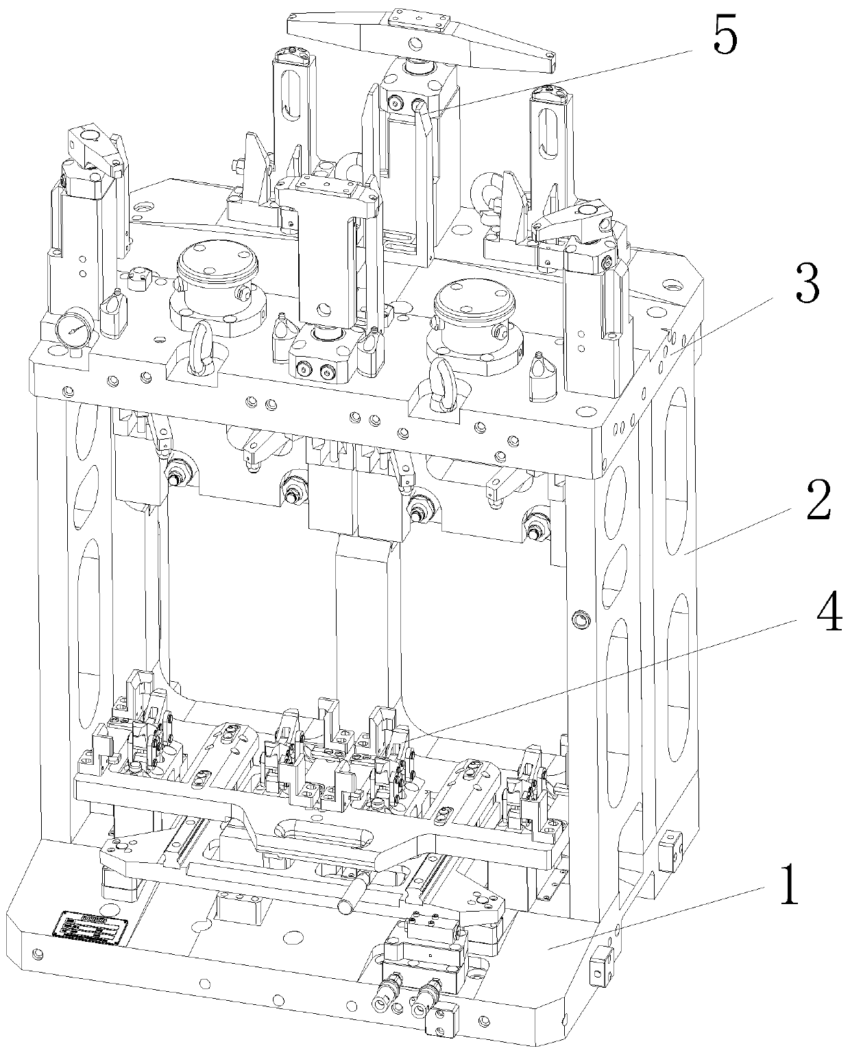
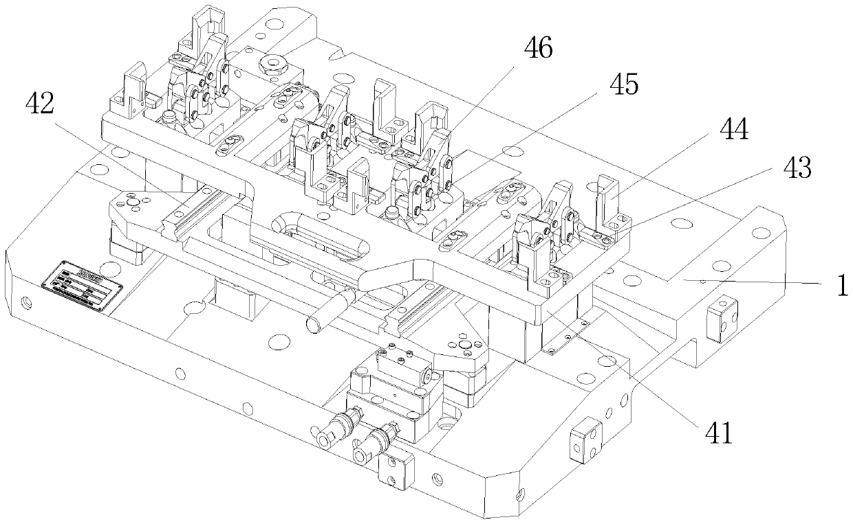
[0024] Such as figure 2 The shown tooling fixture for multi-process processing of reducer shell parts includes a fixture body, the side of the fixture body has a plurality of side clamping mechanisms 4 for vertically clamping the reducer shell, and the top of the fixture body has multiple A top clamping mechanism 5 for horizontally clamping the housing of the reducer. The clamp body includes a base plate 1 for mounting side clamping mechanisms 4 , a support plate 2 for supporting, and a top plate 3 for mounting top clamping mechanisms 5 . In a preferred embodiment of the present invention, two sets of side clamping mechanisms 4 are provided on ...


PUM


Abstract

The invention relates to a tool clamp for multi-process machining of a speed reducer housing part. The full-process machining content of the part under different clamping postures can be completed onone tool clamp at a time, wherein a plurality of side clamping mechanisms used for vertically clamping a speed reducer housing are arranged on the side portion of a clamp body of the tool clamp; and aplurality of top clamping mechanisms used for horizontally clamping the speed reducer housing are arranged on the top of the clamp body. According to the tool clamp for multi-process machining of thespeed reducer housing part, through the special design of the side clamping mechanisms and the top clamping mechanisms and positioning mechanisms, the speed reducer housing part in two different postures can be reliably positioned, all-dimensional machining of the multiple speed reducer housing parts can be achieved through one-time clamping, the machining efficiency is greatly improved, the machining precision is guaranteed, the labor intensity of workers is relieved, and the clamp can be in seamless butt joint with automatic production in the later period.

Description

Technical field: [0001] The invention relates to the technical field of reducer processing, in particular to a fixture for multi-process processing of reducer shell parts. Background technique: [0002] Existing reducer housing 6 such as figure 1 As shown, it is formed by casting. After forming, it needs to be carved, bored, drilled, tapped and other processes. However, due to its complex and irregular structure, each process is completed on different equipment. Multiple handling and positioning, long processing cycle and low processing accuracy. It is also processed by a machining center, which has certain precision requirements for the fixture. When clamping, it requires higher operating requirements for workers. Moreover, the housing of the reducer needs to be processed on multiple surfaces, so it needs to be turned over after a process is processed, and it needs to be repositioned and clamped, which is very inconvenient. Invention content: [0003] In view of the ab...

Claims


Application Information

Patent Timeline
IPC IPC(8): B23Q3/08
CPCB23Q3/061B23Q3/062B23Q3/082
Inventor 陆建华是红波
Owner CHANGZHOU JULING FOUNDRY
Why Eureka
Try Eureka