High-speed railway expanding cement slurry post-grouting bulk material pile composite foundation construction method

A technology for bulk material piles and high-speed railways, which can be used in infrastructure engineering, sheet pile walls, buildings, etc., and can solve problems such as large post-construction settlement, unfavorable construction, and high clearance

Inactive Publication Date: 2020-07-07
CHONGQING UNIV +1
View PDF7 Cites 6 Cited by
  • Summary
  • Abstract
  • Description
  • Claims
  • Application Information

AI Technical Summary

Problems solved by technology

[0003] However, as a kind of flexible pile composite foundation, the traditional crushed stone pile only focuses on the function of the foundation itself, and does not significantly improve the soil between the piles that has a significant impact on the quality of foundation reinforcement, and the post-construction settlement is relatively large; and t

Method used


Image

  • High-speed railway expanding cement slurry post-grouting bulk material pile composite foundation construction method
  • High-speed railway expanding cement slurry post-grouting bulk material pile composite foundation construction method
  • High-speed railway expanding cement slurry post-grouting bulk material pile composite foundation construction method

Examples


Embodiment 1

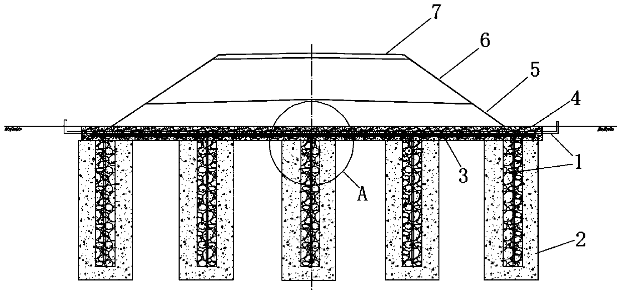
[0037] The construction method of composite foundation of high-speed railway expanded cement slurry post-grouting granular material pile is characterized in that it comprises the following steps:

[0038] 1) Drilling in sections to form holes: Use a small gyroscopic drill to drill the hole, each drill rod is no more than 5 meters in length, and the first drill rod reaches the drilling depth and then connects to the second drill rod. After drilling the depth, connect the third drill rod, and so on, through the connection of the drill rod to form holes in sections until the design pile length is reached.

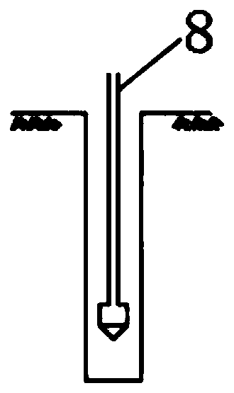
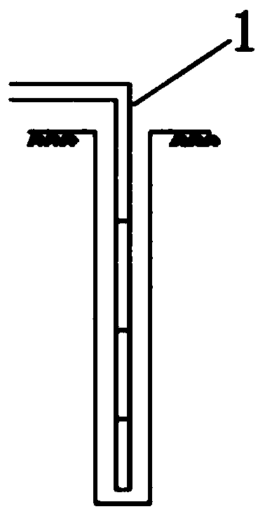
[0039] 2) Place a number of grouting steel pipes (1) of different lengths in the above-mentioned borehole; after the upper end of the grouting steel pipe (1) extends out of the ground, it is bent 90 degrees and protrudes from both sides of the subgrade in the horizontal direction (for convenience Grouting). In the embodiment, the grouting pipe adopts steel pipes, which are connect...

Embodiment 2

[0048] The main structure of this embodiment is the same as that of embodiment 1. Further, in step 1), the length of each drill rod is not more than 5 meters, and the first drill rod is connected to the second drill rod after reaching the drilling depth. After reaching the drilling depth, connect the third drill rod, and so on, through the connection of the drill rod to form holes in sections until the design pile length is reached.

Embodiment 3

[0050] The main structure of this embodiment is the same as that of Embodiment 1. Further, in step 1], the formed pile hole is divided into several sections, each section being no more than 5 meters in length.

[0051] In step 2], the number of grouting steel pipes 1 is the same as the number of pile hole sections, and each grouting steel pipe 1 extends to the bottom of the section, and a distance from the bottom section is 15-30cm (the longest one grouting steel pipe 1 , In the lowest section, should ensure that the lower end is 15-30cm away from the bottom of the hole).

[0052] Several grouting steel pipes of different lengths. In step 7], the grouting pressure and the amount of expansion agent can be adjusted according to the situation to form a reducing pile:

[0053] 1. For a homogeneous foundation, since the earth pressure increases linearly with depth, from the grouting steel pipe 1 extending to the bottom end to the grouting steel pipe 1 extending to the top, the grouting p...


PUM


Abstract

The invention provides a high-speed railway expanding cement slurry post-grouting bulk material pile composite foundation construction method. The high-speed railway expanding cement slurry post-grouting bulk material pile composite foundation construction method comprises the steps that segmented drilling for hole forming is conducted; grouting pipes are placed in a drill hole in a segmented connection mode, and the grouting pipes are bent by 90 degrees and extend out of the two sides of a roadbed in the horizontal direction; a bulk material is put in the drill hole; a reinforced gravel cushion layer is laid on the surface of a foundation; layered filling of embankment soil is carried out on the cushion layer; foundation soil is subjected to consolidated drainage; and expanding cement slurry is injected into the grouting pipes to form rigid pile bodies. The drainage performance of the bulk material is fully utilized to enable inter-pile soil to be subjected to drainage consolidation during embankment filling, the carrying capacity of pile foundations is improved through the expanding cement slurry, properties of the inter-pile soil are improved, and the advantages such as small post-construction settlement are achieved.

Description

Technical field [0001] The invention belongs to the technical field of foundation engineering, and in particular relates to a method for constructing a composite foundation of high-speed railway expanded cement slurry post-grouting granular material piles. Background technique [0002] The rapid development of high-speed railways in my country, but my country’s vast territory and outstanding differences in geological conditions, the soft soil foundations that need to be reinforced are widely distributed, and high-fill and high-backfill foundations are also common in the western region. This is important for the construction of high-speed railways. It is extremely unfavorable. In the actual construction process, the pile-soil composite foundation method is often used to make up for these defects of insufficient foundation bearing capacity. However, it is obvious that the soil of this type of foundation is loose and insufficiently compacted, which leads to a loose pile-soil contact...

Claims


Application Information

Patent Timeline
IPC IPC(8): E02D5/46E02D5/62E02D15/04
CPCE02D5/46E02D5/62E02D15/04
Inventor 刘汉龙丁选明邓鑫龙永红
Owner CHONGQING UNIV
Why Eureka
Try Eureka