Condensation heat exchange pipe and manufacturing and using method thereof

A manufacturing method and technology of a heat exchange tube are applied to a condensation heat exchange tube, and a method for manufacturing and using the condensation heat exchange tube. It can solve problems such as unscientific methods, poor effects, and thinning, and achieve the effects of compact structure, stable operation, and water conservation.

Inactive Publication Date: 2016-05-04
SHANGHAI JIAO TONG UNIV
View PDF6 Cites 3 Cited by
  • Summary
  • Abstract
  • Description
  • Claims
  • Application Information

AI Technical Summary

Problems solved by technology

[0002] In the development process of enhanced heat exchange tubes, adding fins is undoubtedly an efficient way to enhance heat exchange. The main forms of fins are needle ribs, straight ribs, ring ribs, and integral fins (flat fins) represented by air conditioner external units. sheet, triangular corrugated sheet, sinusoidal corrugated sheet, slotted sheet), etc. However, the effect of traditional fins to enhance heat transfer is not good in condenser design
The newly developed condensing tube with a draining ring blocks the growth and thickening of the liquid film by the draining ring, and the condensate is discharged in time, thus reducing the thickness of the liquid film and strengthening the condensation heat transfer, but the draining It is unscientific to arrange the ring vertically to the axis of the condensing heat exchange tube. Condensate will accumulate and grow thicker on the horizontal drainage ring, and the condensate will not overflow and discharge until the thickness of the condensate is thick enough. Therefore, the vertical arrangement design is conducive to condensation. The occurrence of the process and the enhancement of heat transfer, but there are still defects

Method used


Image

  • Condensation heat exchange pipe and manufacturing and using method thereof
  • Condensation heat exchange pipe and manufacturing and using method thereof
  • Condensation heat exchange pipe and manufacturing and using method thereof

Examples


Embodiment Construction

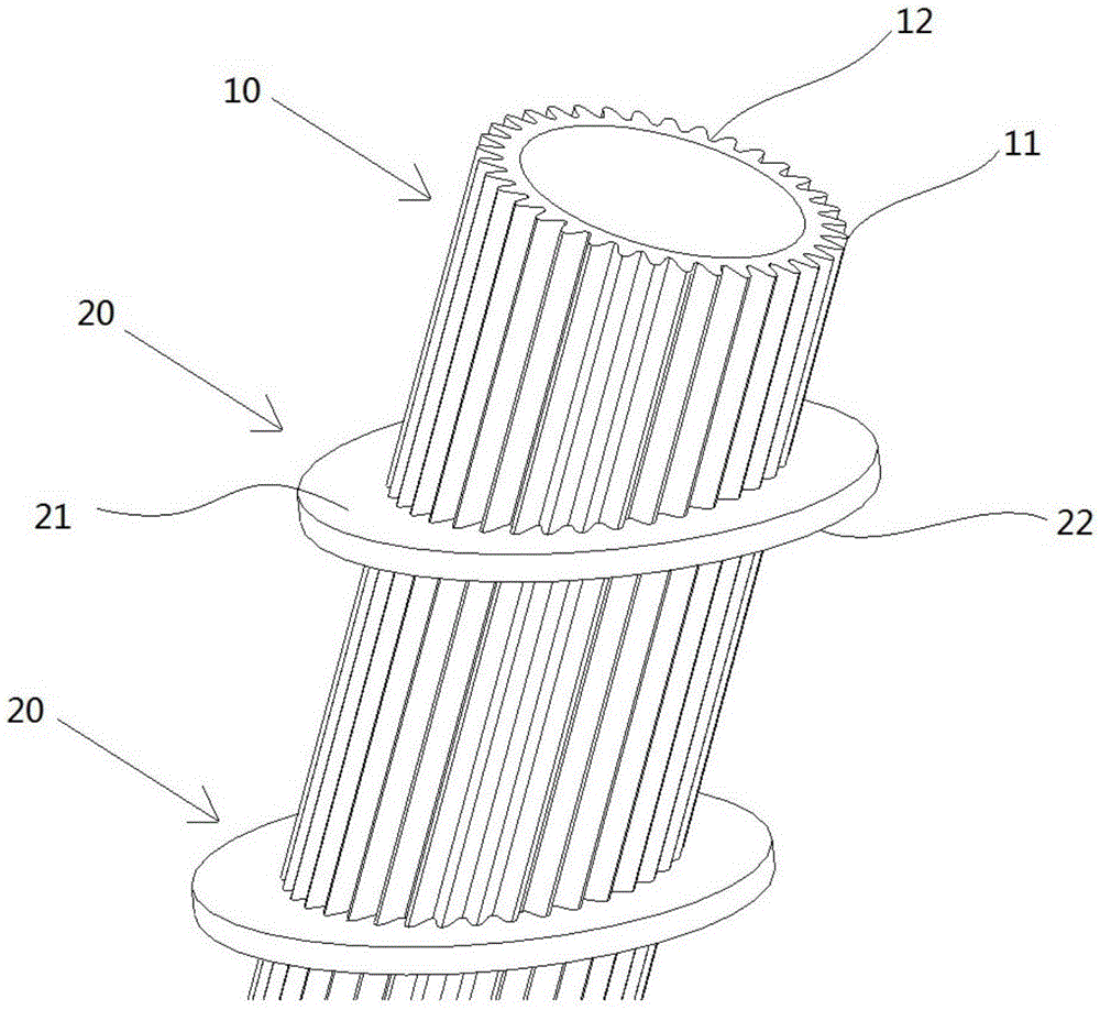
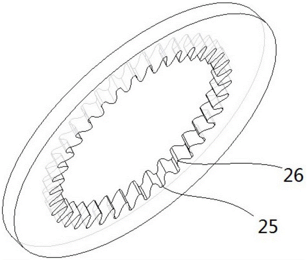
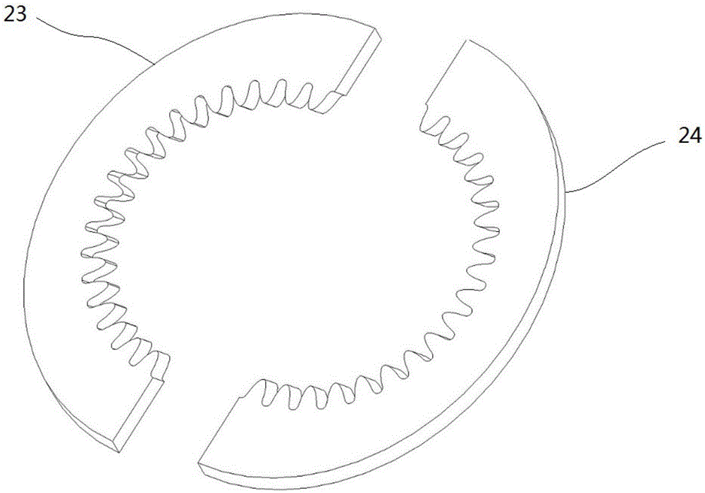
[0033] Figure 1-Figure 3 A preferred embodiment of the condensation heat exchange tube provided by the present invention is shown.

[0034] Such as Figure 1-Figure 3 As shown, the condensing heat exchange tube in this specific embodiment includes a heat exchange base tube 10 and a plurality of fins 20 , and the fins 20 are sleeved on the outside of the heat exchange base tube 10 . The fin 20 has a first surface 21 , the first surface 21 is a plane, the heat exchange base pipe 10 extends along the axis, and the plane where the first surface 21 of the fin 20 is located obliquely intersects with the axis of the heat exchange base pipe 10 . The included angle between the fin plane and the axis of the heat exchange base tube can be determined by experiments. After searching through the application, in order to obtain a better condensation heat transfer effect, the angle between the plane where the first surface 21 of the fin 20 is located and the axis of the heat transfer base ...


PUM


Abstract

The invention provides a condensation heat exchange pipe. The condensation heat exchange pipe comprises a heat exchange base pipe and a plurality of fins connected to the outside of the heat exchange base pipe in a sleeving mode. Each fin is provided with a first surface which is a plane. The heat exchange base pipe is provided with an axis and extends along the axis. The plane where the first surface of each fin is located and the axis of the heat exchange base pipe intersect obliquely. Accumulating of condensation water on the fins can be effectively inhibited through the condensation heat exchange pipe provided by the invention. The invention further provides a manufacturing and using method of the condensation heat exchange pipe.

Description

technical field [0001] The invention relates to a condenser, in particular to a condensation heat exchange tube. The condensing heat exchange tube provided by the present invention is especially suitable for the working condition of the condensation of steam containing non-condensable gas, such as recovery of water in flue gas at the tail of a boiler. The invention also provides a method for manufacturing and using the condensing heat exchange tube. Background technique [0002] In the development process of enhanced heat exchange tubes, adding fins is undoubtedly an efficient way to enhance heat exchange. The main forms of fins are needle ribs, straight ribs, ring ribs, and integral fins (flat fins) represented by air conditioner external units. fins, triangular corrugated fins, sinusoidal corrugated fins, slotted fins), etc. However, the effect of traditional fins to enhance heat transfer is not good in condenser design. The newly developed condensing tube with a drainin...

Claims


Application Information

Patent Timeline
IPC IPC(8): F28F1/30F28F21/08
CPCF28F1/30F28F21/082F28F21/085F28F2275/127F28F2275/16
Inventor 茅锦达王恩禄徐煦万丛李凯
Owner SHANGHAI JIAO TONG UNIV
Why Eureka
Try Eureka