Vacuum degree gas saving regulation system

A technology for adjusting the system and vacuum degree, applied in the field of molten steel refining outside the furnace, can solve the problems of inability to adjust, increase the cost, unfavorable process flow, etc., and achieve good economic benefits, shorten the processing time, and save the effect of working steam.

Inactive Publication Date: 2011-08-17
CHINA NAT HEAVY MACHINERY RES INSTCO
View PDF1 Cites 5 Cited by
  • Summary
  • Abstract
  • Description
  • Claims
  • Application Information

AI Technical Summary

Problems solved by technology

[0002] The steam jet pump is RH (Molten Steel Vacuum Circulation Degassing Process, which was jointly developed by Ruhrstahl and Heraeus in 1959, taking the first letter of the company to call this process RH), VD (Vacuum decarburization), VOD (Vacuum Oxygen decarburization) and other key equipment for vacuum refining, its function is to pump the molten steel environment into a high vacuum state, the highest can reach about 67Pa; the existing known The technology is: in the process of molten steel processing, the vacuum degree that can be maintained is guaranteed by the working capacity of the pumps at all levels, and cannot be adjusted. The load is different, the vacuum pump cannot be accurately stabilized at the vacuum required by the process
[0003] The disadvantage of no vacuum degree adjustment is: in some refining processes, such as oxygen blowing decarburization, vacuum feeding,

Method used


Image

  • Vacuum degree gas saving regulation system
  • Vacuum degree gas saving regulation system
  • Vacuum degree gas saving regulation system

Examples


Embodiment 1

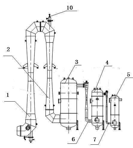
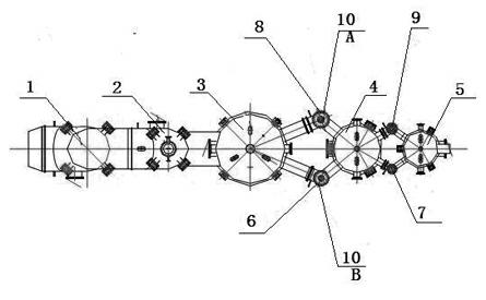
[0019] figure 1 , 2 A four-stage vacuum pump embodiment is given, including: the first booster pump 1, the second booster pump 2, the first condenser 3, the second condenser 4, the third condenser 5, the first jet pump 6 and the second jet Pump 7 and first auxiliary jet pump 8, second auxiliary jet pump 9, first booster pump 1 communicates with second booster pump 2, second booster pump 2 communicates directly with first condenser 3, first condenser 3 is communicated with one port of the second condenser 4 through the first jet pump 6, the first condenser 3 is communicated with the other port of the second condenser 4 through the first auxiliary jet pump 8, and the second condenser 4 is communicated through the second jet pump 7 communicates with one port of the third condenser 5, and the second condenser 4 communicates with the other port of the third condenser 5 through the second auxiliary jet pump. The nozzles 13 of the second booster pump 2 , the first jet pump 6 and th...

Embodiment 2

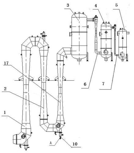
[0024] image 3 , 4 An embodiment of a five-stage vacuum pump is given. The structure of this embodiment is basically the same as that of Embodiment 1. The difference is that there are three-stage booster pumps. The three-stage booster pumps are connected in sequence. The third booster pump 17 is directly connected to the first condenser 3. connected. All or part of the first jet pump 6 and the first auxiliary jet pump 8 , and the third booster pump 17 are equipped with a vacuum degree throttling adjustment device 10 .

[0025] When in use, it is also divided into two steps of rough vacuum treatment and deep vacuum treatment.

[0026] According to the needs of the actual situation, the vacuum pump system with different stages only needs to add or reduce the number of vacuum pumps, and install all or part of the booster pump, jet pump and auxiliary jet pump directly connected with the first condenser 3 Vacuum degree air-saving adjustment device 10.


PUM


Abstract

The invention relates to the technical field of the external refining of a steel liquid furnace, and in particular relates to a vacuum degree gas saving regulation system aiming at a water vapour ejector pump. The vacuum degree gas saving regulation system comprises multi-level booster pumps, two-level ejector pumps, two-level assistant ejector pumps and three condensers and is characterized in that the multi-level booster pumps are successively communicated; the last-level booster pump is directly communicated with the first condenser; the first condenser is communicated with one port of the second condenser by the first ejector pump; the first condenser is communicated with the other port of the second condenser by the first assistant ejector pump; the second condenser is communicated with one port of the third condenser by the second ejector pump; the second condenser is communicated with the other port of the third condenser by the second assistant ejector pump; and the nozzles of the last-level booster pump, the first ejector pump and the first assistant ejector pump are respectively provided with a vacuum degree gas saving regulation device. According to the technical requirements, the vacuum degree is regulated by the system, the raw materials are saved, and the refining technology is satisfied.

Description

technical field [0001] The invention relates to the technical field of molten steel refining outside the furnace, in particular to a vacuum degree and gas-saving adjustment system for a steam jet pump. Background technique [0002] The steam jet pump is RH (Molten Steel Vacuum Circulation Degassing Process, which was jointly developed by Ruhrstahl and Heraeus in 1959, taking the first letter of the company to call this process RH), VD (Vacuum decarburization), VOD (Vacuum Oxygen decarburization) and other key equipment for vacuum refining, its function is to pump the molten steel environment into a high vacuum state, the highest can reach about 67Pa; the existing known The technology is: in the process of molten steel processing, the vacuum degree that can be maintained is guaranteed by the working capacity of the pumps at all levels, and cannot be adjusted. Depending on the load, the vacuum pump cannot accurately stabilize the vacuum required by the process. [0003] The ...

Claims


Application Information

Patent Timeline
IPC IPC(8): C21C7/10
Inventor 方杞青任彤张钰傅登峰陈亚文吴建龙曹海玲张明
Owner CHINA NAT HEAVY MACHINERY RES INSTCO
Why Eureka
Try Eureka