Rail-frame integrated wall-attached support device and jacking method thereof
A supporting device and integrated technology, which is applied to the accessories of scaffolding, housing structure support, housing structure support, etc., can solve the problems of integrated platform anti-torsion deflection in the air, difficult to achieve large bearing capacity requirements, and high manufacturing and processing technology requirements. , to achieve the effect of improving torsion resistance, good economic benefits, and large bearing capacity
- Summary
- Abstract
- Description
- Claims
- Application Information
AI Technical Summary
Problems solved by technology
Method used
Image

Examples
Embodiment 1
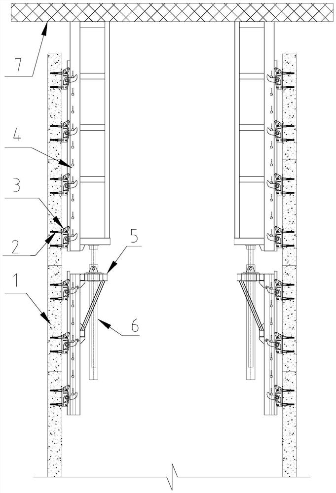
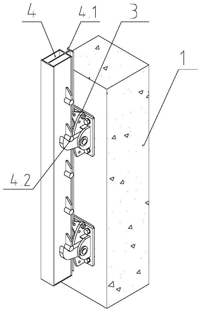
[0040] refer to Figure 1 to Figure 5b , in this embodiment, a rail-frame-integrated wall-attached support device includes a wall-attached support, and also includes a wall-attached connector 2 and a guide rail column 4, wherein,
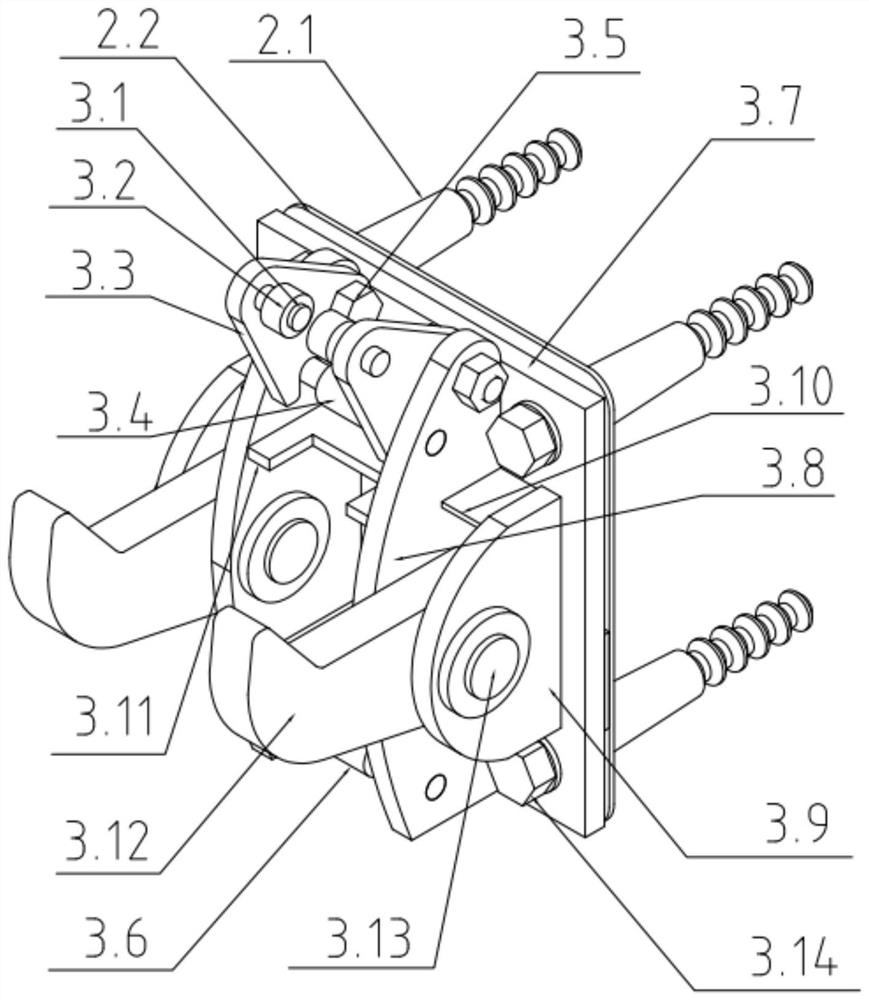
[0041] Attached wall bearing 3 comprises base plate 3.7, supporting claw 3.12, supporting ear plate and anti-side guiding mechanism, and supporting ear plate is fixed on one side of base plate 3.7, and supporting claw 3.12 is supported on supporting ear plate and is connected with it in rotation (an attached The wall support 3 is provided with at least one supporting claw 3.12 and a pair of supporting lugs. In this embodiment, two supporting claws 3.12 and two pairs of supporting lugs are set as an example), and the supporting claws 3.12 can be turned freely. Claw 3.12 is used to support the load-bearing rod 4.2 of guide rail column 4, anti-side guide mechanism includes inner side anti-side guide wheel and outer side anti-side guide wheel 3.2, inner...
Embodiment 2
[0064] refer to Figure 6a with Figure 6b, The matching method between the wall-attached support 3 and the rail column 4 in this embodiment is slightly different from that in Embodiment 1.
[0065] In this embodiment, the supporting claw 3.12 and the anti-side guide mechanism are consistent with the operating principle of embodiment 1, the difference is that a group of hanging shoes 3.15 (i.e. the supporting device, A groove is formed by welding multiple plates), the oil cylinder bracket 5 can be hung on the hanging shoe 3.15 through the hook, and supported on the same group of wall-attached supports 3 with the guide rail column 4 at the same time, using this shared wall-attached support 3, the position of the oil cylinder support 5 can be moved up by one structural layer, and the number of installations of the wall-attached supports 3 can be reduced.
Embodiment 3
[0067] refer to Figure 7a with Figure 7b , The matching method between the wall-attached support 3 and the rail column 4 in this embodiment is slightly different from that in Embodiment 1.
[0068] In this embodiment, the supporting claw 3.12 and the guiding anti-side mechanism are consistent with the operating principles of Embodiments 1 and 2, the difference lies in the following points:
[0069] 1. The number of supporting claws 3.12 of each wall-attached support 3 is one. At this time, in order to meet the assembly requirements after the structure of the supporting claws is changed, the load-bearing rod structure of the guide rail column 4 is also changed, and the corresponding position is adjusted to Between the two webs of the guide rail column; 2. A group of hook lugs 3.16 (that is, the supporting device, the structure of which is the same as that of the hanging shoe 3.15 in Embodiment 2) are respectively added to the left and right sides of the outer side of the sup...
PUM
 Abstract
Description
Claims
Application Information
 - Generate Ideas
- Intellectual Property
- Life Sciences
- Materials
- Tech Scout
- Unparalleled Data Quality
- Higher Quality Content
- 60% Fewer Hallucinations
Browse by: Latest US Patents, China's latest patents, Technical Efficacy Thesaurus, Application Domain, Technology Topic, Popular Technical Reports.
© 2025 PatSnap. All rights reserved.Legal|Privacy policy|Modern Slavery Act Transparency Statement|Sitemap|About US| Contact US: help@patsnap.com