
Rail frame integrated support jacking system and jacking method for integrated platform

An integrated platform and one-piece technology, which is applied to the scaffolding supported by the building structure, the accessories of the scaffolding, the structural support of the building, etc., can solve the problems of no anti-falling, anti-torsion offset of the integrated platform in the air, high manufacturing and processing technology, and achieve reduction The effect of labor intensity of workers, improvement of torsion resistance, and good economic benefits

Active Publication Date: 2022-01-18
CHINA CONSTR THIRD ENG BUREAU GRP CO LTD
View PDF4 Cites 0 Cited by
  • Summary
  • Abstract
  • Description
  • Claims
  • Application Information

AI Technical Summary

Problems solved by technology

The climbing formwork construction platform is limited by factors such as the form of the support system and the attachment position of the fulcrum, and it is difficult to achieve a large load-carrying capacity requirement
The low-position top formwork integrated platform has good load-carrying capacity, but the size of the supporting system components is huge, and it must be designed according to the structural characteristics of each project, which is difficult to be used for multiple projects, and the economy is poor; and because of its few fulcrums (generally 4~6, must be arranged at the position where there are walls at both ends of the support beam), the integrated platform is prone to anti-torsion deviation in the air, and there is no anti-fall setting, which poses a safety hazard
The supporting position of the micro-convex top form integrated platform is relatively flexible, but because the load-bearing parts must be part of the formwork, they must be customized according to the height of the structure, the manufacturing process is high, and the versatility is not ideal; a single set of load-bearing parts weighs 2.5 Tons, installed at the same time as the formwork, the installation and dismantling turnover is labor-intensive

Method used


Image

  • Rail frame integrated support jacking system and jacking method for integrated platform
  • Rail frame integrated support jacking system and jacking method for integrated platform
  • Rail frame integrated support jacking system and jacking method for integrated platform

Examples


Embodiment 1

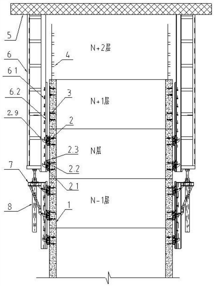
[0045] refer to Figure 1 to Figure 7b , in this embodiment, a rail-frame integrated support jacking system for an integrated platform, including a wall-attached connector 3, a wall-attached support 2, a cylinder support 7, a hydraulic cylinder 8, a support column 6, and an integrated construction platform 5, of which,

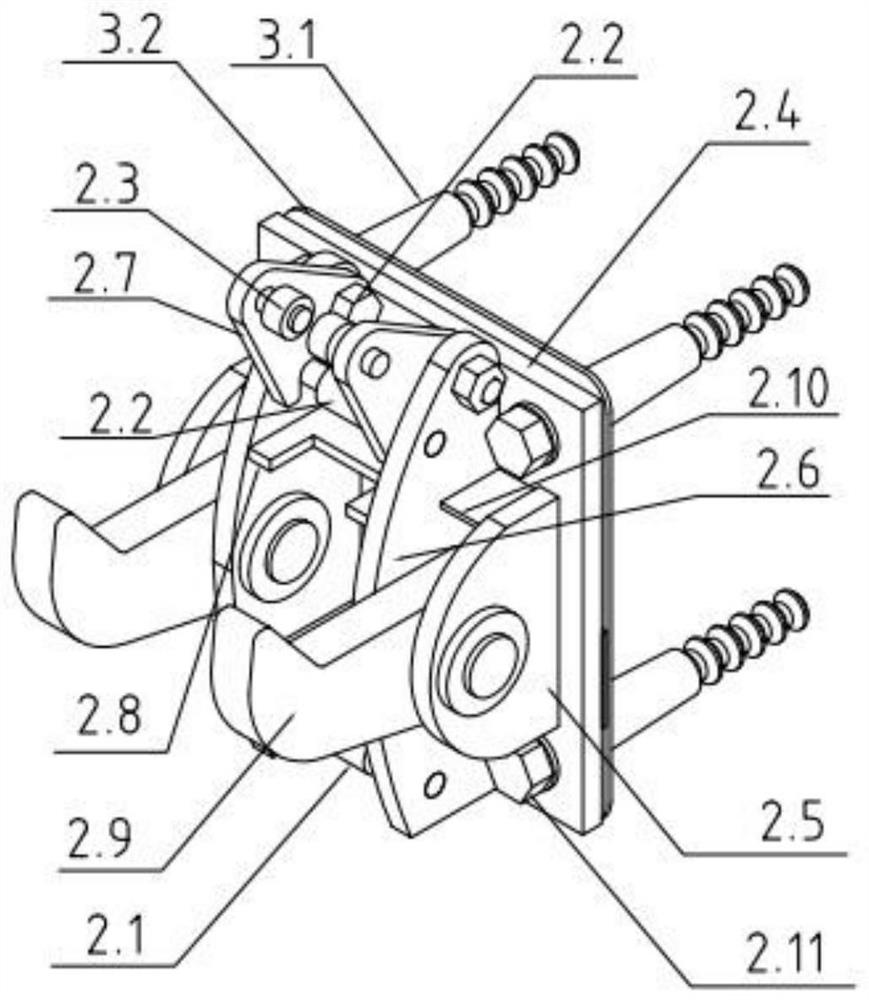
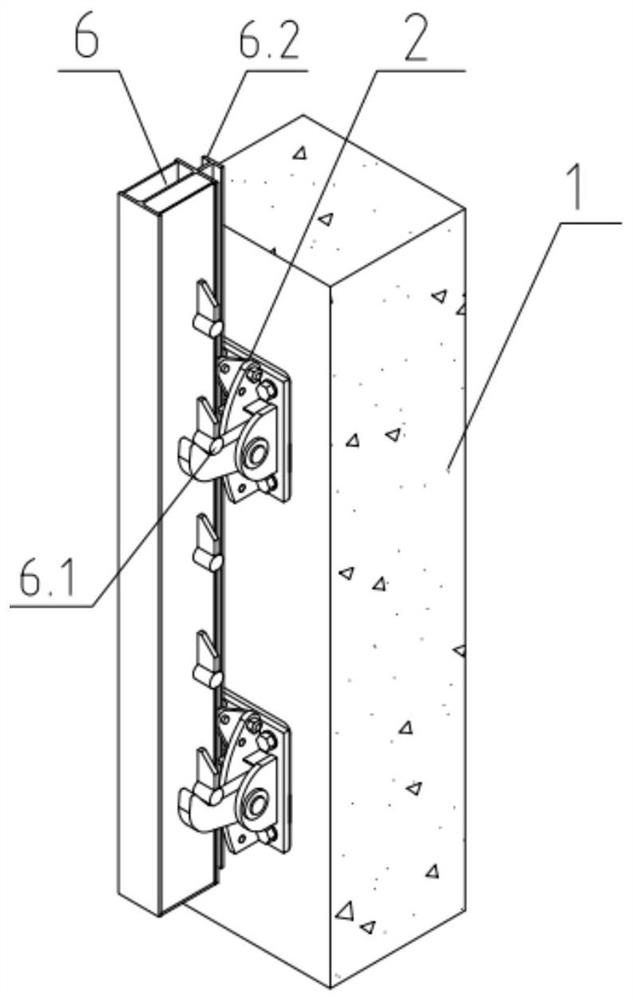
[0046] The wall-attached support 2 is detachably installed on the surface of the concrete wall 1 through the corresponding wall-attached connector 3. The wall-attached support 2 is equipped with a supporting hook 2.9 that can be turned freely, and the support column 6 and the cylinder bracket 7 are supported on it. Respectively corresponding to the supporting hooks 2.9 of the wall-attached support 2 (in this embodiment, the support column 6 and the oil cylinder bracket 7 are correspondingly hung on the two wall-attached supports 2), the support column 6 is located above the oil cylinder support 7, and the oil cylinder A hydraulic cylinder 8 is installed on th...

Embodiment 2

[0069] refer to Figure 8a and Figure 8b , The difference between this embodiment and Embodiment 1 is that a group of hanging shoes 2.12 are respectively added on the left and right sides of the support hook 2.9 of the wall bearing 2 in the present embodiment to support the cylinder support 7.

[0070] In this embodiment, the oil cylinder bracket 7 is hooked on the hanging shoe 2.12 of the wall support 2 through the hanging claw (with an elastic reset mechanism, which can realize the automatic flip and reset of the hanging claw), and the oil cylinder bracket 7 and the supporting column 6 are simultaneously supported to On the same group of wall-attached supports 2, the position of the oil cylinder support 7 can be moved up by one structural layer without changing the safety of the support system by adopting this method of sharing the wall-attached supports 2 ), nested together with the support column 6, reducing the number of setting of the wall-attached support 2, and also ...

Embodiment 3

[0072] refer to Figure 9a to Figure 9g , Embodiment 3 is consistent with the operating principle of the supporting claw 2.9 and the anti-side guiding mechanism of Embodiment 1 and 2, the difference is that Embodiment 3 has carried out the following adjustments on the basis of Embodiment 2:

[0073] 1. In Example 3, the number of supporting hooks 2.9 in each set of wall-attached support 2 is 1, and the load-bearing mode of supporting column 6 and wall-attached support 2 is changed from double hooks on both sides of the column to a single hook in the abdominal cavity of the column claw;

[0074] 2. In Example 3, a set of hook lugs 2.13 are added on the outside, left, and right sides of the supporting hook claw 2.9. The function is similar to that of the hanging boot 2.12, and the structure is slightly changed. Its function is to hook the oil cylinder bracket 7, and through the hook 7.1 It is fixed on the hook ear plate 2.13. With this method of sharing the wall-attached suppor...


PUM


Abstract

The invention discloses a rail-frame integrated support jacking system for an integrated platform, comprising a wall-attached connector, a wall-attached support, an oil cylinder support, a hydraulic cylinder, a support column and a construction integrated platform, wherein the wall-attached support It can be detachably installed on the surface of the concrete wall through the corresponding wall-attached connector, and the supporting claws that can be turned freely are installed on the wall-attached support. , the support column is located above the oil cylinder bracket, a hydraulic cylinder is installed on the oil cylinder support, and the piston rod of the hydraulic cylinder is connected with the support column to drive it to lift. The invention also proposes a jacking method for a rail-frame integrated support jacking system of an integrated platform. The rail frame integrated support jacking system for the integrated platform proposed by the present invention is light in size, flexible in installation and disassembly, capable of anti-torsion, safe and reliable, has a large bearing capacity, and can be used in turnover.

Description

technical field [0001] The invention relates to the technical field of building construction, in particular to a rail-frame integrated support jacking system for an integrated platform and a jacking method thereof. Background technique [0002] In building construction, the integrated platforms currently used for the core tube construction of super high-rise buildings mainly include climbing formwork construction platforms and top formwork construction integrated platforms. Micro-convex top mold integration platform. Climbing formwork construction platforms are limited by factors such as the form of the support system and the attachment position of the fulcrum, making it difficult to achieve a large load-carrying capacity requirement. The low-position top formwork integrated platform has good load-carrying capacity, but the size of the supporting system components is huge, and it must be designed according to the structural characteristics of each project, which is difficul...

Claims


Application Information

Patent Timeline
Patent Type & Authority Patents(China)
IPC IPC(8): E04G3/28E04G5/04E04G11/28
CPCE04G3/28E04G5/046E04G11/28E04G2003/286
Inventor 王辉王开强王磊李迪陈凯赵翼鸿朱磊磊王建春赵金明
Owner CHINA CONSTR THIRD ENG BUREAU GRP CO LTD
Features
  • Generate Ideas
  • Intellectual Property
  • Life Sciences
  • Materials
  • Tech Scout
  • Unparalleled Data Quality
  • Higher Quality Content
  • 60% Fewer Hallucinations
Learn More