Slag conveying device of biomass gas furnace

A biomass gas and conveying device technology, which is applied in the treatment of combustion products, combustion methods, and removal of solid residues, etc., can solve the problems of affecting the scraping efficiency, increasing the gap, and easily tilting the scraper.

Pending Publication Date: 2020-07-07
安徽乾丰新型肥料有限公司
View PDF0 Cites 0 Cited by
  • Summary
  • Abstract
  • Description
  • Claims
  • Application Information

AI Technical Summary

Problems solved by technology

At present, the slag that falls on the bottom of the biomass gas furnace is transported to the outside of the biomass gas furnace through the scraper conveying mechanism. The structure of the scraper conveying mechanism is to weld several scrapers on the chain, and the scraper directly scrapes off the bottom of the biomass gas furnace. The slag on the wall is transported to the outside of the biomass combustion furnace along the bottom wall of the pipeline; however, after the existing scraper conveying mechanism is used for a long time, the angle of the scraper is easy to tilt, and it is difficult to travel along the original track, which affects the efficiency of scraping ; and the scraper is affected by the solidified slag on the pipeline, there is a gap between a certain position of the scraper and the bottom wall of the pipeline, and the gap will continue to increase, requiring frequent follow-up maintenance

Method used


Image

  • Slag conveying device of biomass gas furnace
  • Slag conveying device of biomass gas furnace
  • Slag conveying device of biomass gas furnace

Examples


Embodiment Construction

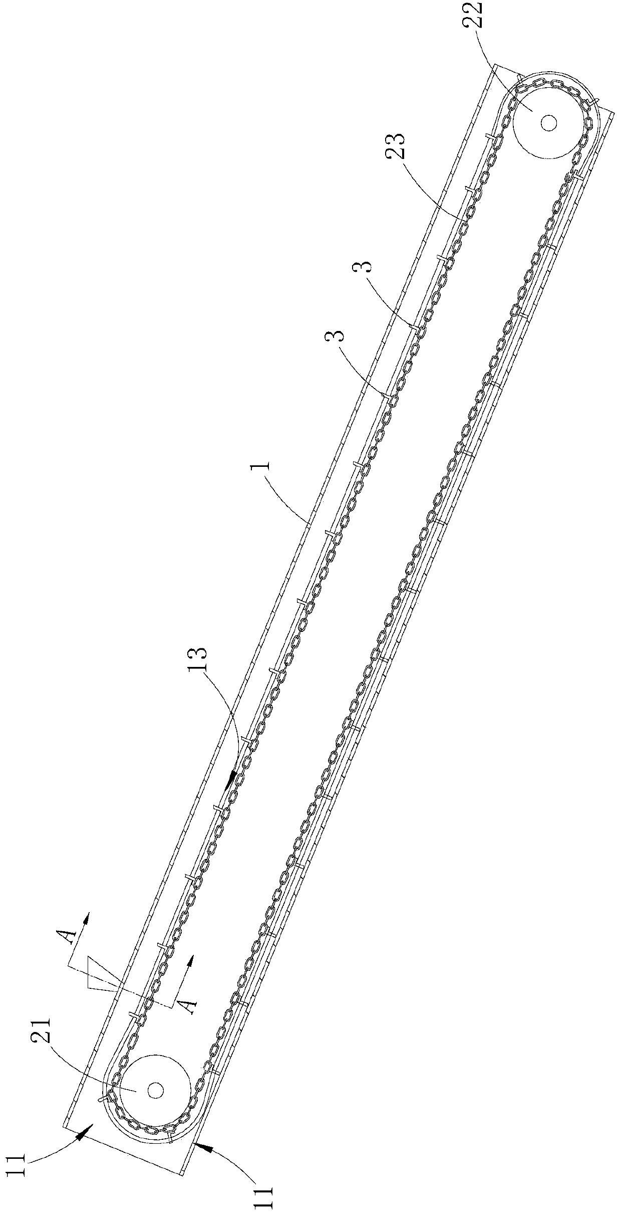
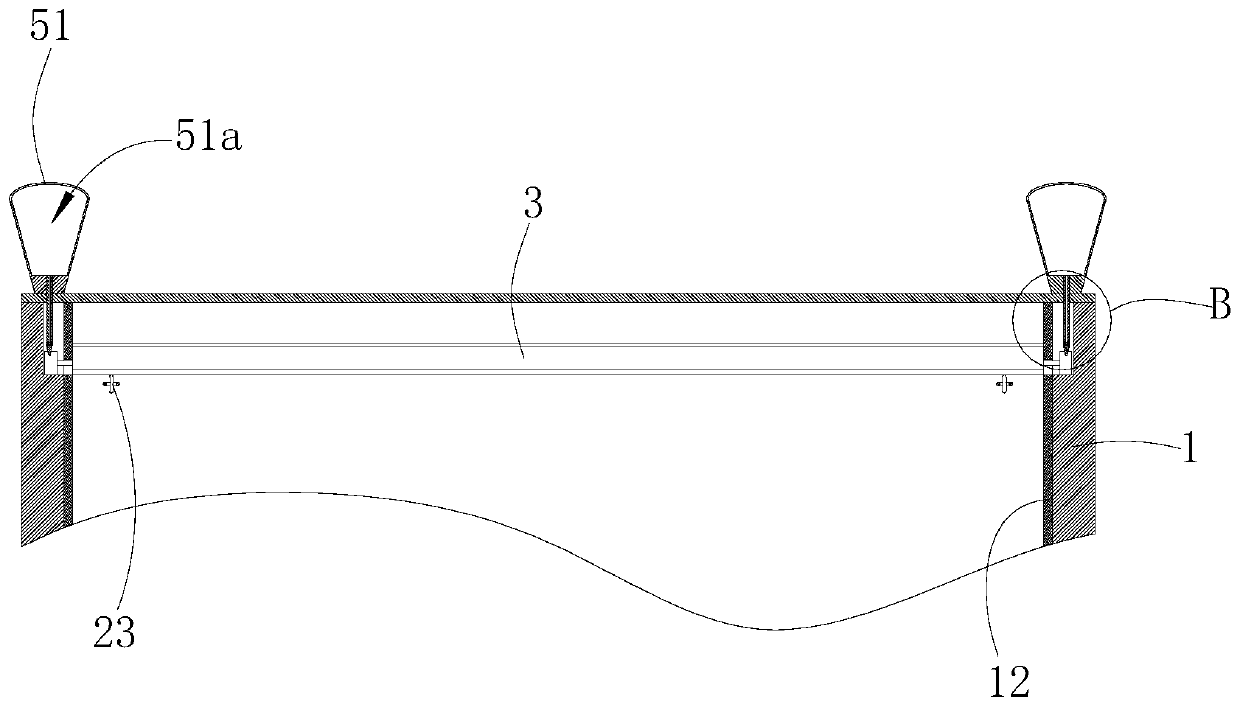
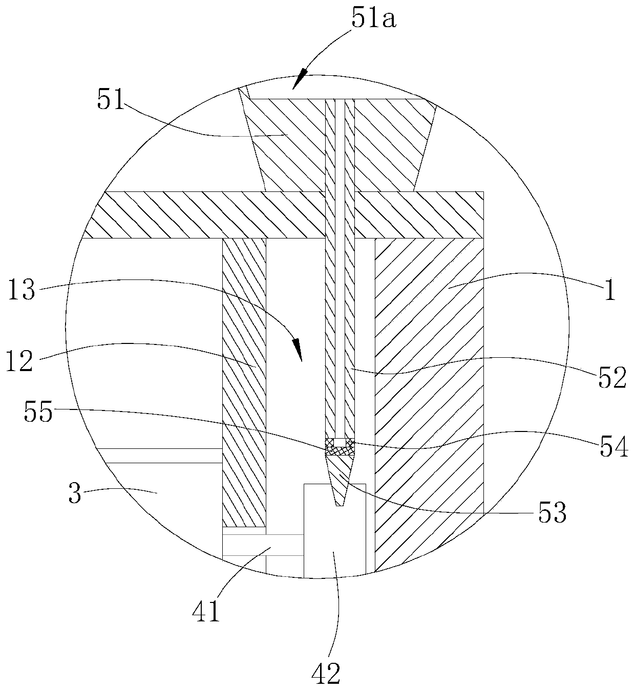
[0015] Such as Figures 1 to 3 shown

[0016] The slag conveying device includes a conveying pipeline 1 , a chain transmission mechanism, two sets of lubricating components and a plurality of scrapers 3 .

[0017] The conveying pipe 1 is a square pipe, the lower end of the conveying pipe 1 extends into the bottom of the biomass gas furnace, the upper end of the conveying pipe 1 protrudes outside the biomass gas furnace, and the bottom wall and the upper end of the upper end of the conveying pipe 1 are provided with a slag outlet 11 for discharging slag .

[0018] The chain transmission mechanism includes a driving roller 21, a driven roller 22 and two chains 23. The two chains 23 are tensioned outside the driving roller 21 and the driven roller 22. The driving roller 21 is driven by an external motor, and multiple scrapers 3 are sequentially Welded on the two chains 23 at intervals, the movement track of the end of the scraper 3 is in contact with the lower inner wall of the...


PUM


Abstract

The invention provides a slag conveying device of a biomass gas furnace. The slag conveying device comprises a conveying pipeline, a chain transmission mechanism and a plurality of scraping plates, wherein one end of the conveying pipeline extends into the bottom of the biomass gas furnace, and the other end of the conveying pipeline extends out of the outer side of the biomass gas furnace; a chain of the chain transmission mechanism is tensioned on the outer sides of a driving roller and a driven roller; a plurality of scraping plates are sequentially and fixedly connected to the chain at intervals; sliding grooves are formed in the two side walls of the conveying pipeline along the movement tracks of the scraping plates correspondingly; track assemblies are arranged on the two sides of the scraping plates correspondingly; one of the ends of transmission shafts of the track assemblies is fixedly connected with the corresponding side walls of the scraping plates, and the other one of the ends of the transmission shafts extends into the corresponding sliding grooves; and sliding wheels are mounted on the transmission shafts extending into the sliding grooves and matched with the corresponding sliding grooves. The track assemblies are matched with the sliding grooves of the conveying pipeline, the stability of the movement tracks of the scraping plates is limited, and the scraping plates are forced to make contact with the bottom wall of the inner side of the conveying pipeline all the time. After long-time use, the inclination angles of the scraping plates are decreased, thescraping plates advance along the original tracks, and the interval of subsequent maintenance is greatly prolonged.

Description

technical field [0001] The invention relates to a slag conveying device of a biomass gas furnace. Background technique [0002] Large-scale biomass gas furnaces are widely used in large-scale industrial enterprises, and can supply a large amount of steam for enterprises. The biomass fuel of large-scale biomass gas furnaces will leave a large number of residues after burning. The above-mentioned residues have the characteristics of high temperature, high viscosity, and easy solidification. Need Timely transport from the bottom of the biomass gas furnace. At present, the slag that falls on the bottom of the biomass gas furnace is transported to the outside of the biomass gas furnace through the scraper conveying mechanism. The structure of the scraper conveying mechanism is to weld several scrapers on the chain, and the scraper directly scrapes off the bottom of the biomass gas furnace. The slag on the wall is transported to the outside of the biomass combustion furnace along...

Claims


Application Information

Patent Timeline
Patent Type & Authority Applications(China)
IPC IPC(8): F23J1/06F23J9/00F23J3/00
CPCF23J1/06F23J3/00F23J9/00
Inventor 张卫卫吴安昌王恒杨佩佩沈冰涛
Owner 安徽乾丰新型肥料有限公司
Why Eureka
Try Eureka