Vacuum temperature fuse, series battery row, parallel battery row and battery pack

A temperature fuse and vacuum technology, which is applied to battery pack components, batteries, circuits, etc., can solve the problem of thermal runaway increase of the monomer, and achieve the effect of small size, relatively small size, and convenient use

Active Publication Date: 2022-04-29
JIAXING MODULE BONDING TECH CO LTD +1
View PDF11 Cites 0 Cited by
  • Summary
  • Abstract
  • Description
  • Claims
  • Application Information

AI Technical Summary

Problems solved by technology

After the capacity of the monomer increases, the risk of thermal runaway of the monomer also increases accordingly

Method used


Image

  • Vacuum temperature fuse, series battery row, parallel battery row and battery pack
  • Vacuum temperature fuse, series battery row, parallel battery row and battery pack
  • Vacuum temperature fuse, series battery row, parallel battery row and battery pack

Examples


Embodiment 1

[0064] The temperature fuse is an effective slow-fuse protection element. When one of the conductors at both ends of its electrical connection is overheated, it will be conducted to its own heat-sensitive material and thermally blown, thereby disconnecting an electrical appliance that disconnects the circuit. For overheating protection of circuits and electrical equipment. When the thermal runaway of the power battery will generate high heat, the bus bar electrically connected to its pole will be the first to receive heat spread. However, the existing fuses cannot be used in the thermal protection of groups of new energy power batteries, because the molten metal will flow, and the smart terminal is vibrating, which will easily cause the liquid metal to flow to other positions in the battery module. A short circuit between normal working batteries is brought about, which in turn leads to new and greater safety risks.

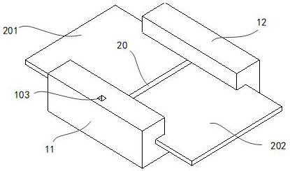
[0065] Embodiment 1 provides a vacuum temperature fuse 1 w...

Embodiment 2

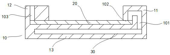
[0119] Embodiment 2 provides a vacuum thermal fuse 1 , which differs from Embodiment 1 mainly in the position of the vacuum suction port 101 .

[0120] As a preferred technical solution, the vacuum suction port 101 is located on the lower surface of the first end of the fuse bar 20 .

[0121] according to Figure 7-Figure 8 , the vacuum suction port 101 is located on the lower surface of the fuse bar 20, and makes the vacuum suction channel 102 communicate with the fuse bar 20. The path of the vacuum suction channel 102 is short, and the fuse bar 20 in the molten state only depends on its own weight and vibration. Just can enter in the vacuum cavity 30.

[0122] During the process of changing the fuse strip 20 from a non-fuse state to a fuse state, when the second end of the fuse strip 20 has not entered a completely melted state, the fuse strip 20 at the position of the vacuum suction port 101 first falls directly into the vacuum chamber 30 Inside: due to the viscosity insi...

Embodiment 3

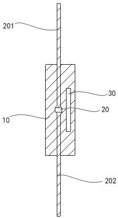
[0127] The vacuum temperature fuse 1 of embodiment 1 is applied to the series battery row, according to Figure 9 , the embodiment provides a series battery row, comprising:

[0128] A plurality of single cells 40, the single cells 40 include a positive pole 401 and a negative pole;

[0129] A plurality of bus bars, each bus bar including a fused bus bar. The fusing busbar includes a first conductor 201 electrically connected to the positive pole 401 of a single battery 40, a second conductor 202 electrically connected to the negative pole of an adjacent single battery 40, and the vacuum temperature of Embodiment 1-2 Fuse 1; preferably, the bus bar electrically connects the positive pole 401 and the negative pole between the adjacent single cells 40 arranged in the previous sequence, and electrically connects the negative pole and the positive pole between the single cells 40 arranged in the subsequent sequence Pole 401; the combination of each first conductor 201, second co...


PUM


Abstract

The invention provides a vacuum temperature fuse, a series battery row, a parallel battery row and a battery pack, the vacuum temperature fuse comprises an insulation shell, the insulation shell comprises a bottom plate, a first side part and a second side part, the first side part and the second side part extend upwards from the two sides of the bottom plate, and a conductor accommodating channel is formed between the first side part and the second side part; the fusing strip is a conductor and is arranged in the conductor accommodating channel; the fusing strip is used for being electrically connected and thermally connected with the first conductor and the second conductor respectively; the vacuum cavity is arranged in the insulating shell, and the vacuum cavity is in local contact with the fusing strip through a vacuum suction port; the fusing strip in the non-molten state can seal the vacuum suction opening, and the fusing strip in the molten state can be sucked into the vacuum cavity through the vacuum suction opening. According to the invention, through the vacuum temperature fuses, the problem of harm blocking of thermal runaway single batteries, which needs to be solved urgently in the field of power batteries, is solved, and the battery row and the battery pack with good single thermal runaway battery harm inhibition capability are provided.

Description

technical field [0001] The invention relates to the field of new energy power batteries, in particular to a vacuum temperature fuse, a series battery row, a parallel battery row and a battery pack. Background technique [0002] As the capacity demand of the power battery group application increases, the current between the battery series circuits increases accordingly. At present, the method of increasing the capacity of a single battery is mostly used to reduce costs and increase efficiency. The series circuit is the main current channel, the series structure of single cells is the most basic current supply unit, and the series bus bar between adjacent cells is one of the most basic series bridges of the series circuit. After the monomer capacity increases, the risk of thermal runaway of the monomer also increases accordingly. How to fuse and electrically isolate the cells in the series circuit as soon as possible after the thermal runaway of the cells, so as not to affec...

Claims


Application Information

Patent Timeline
Patent Type & Authority Applications(China)
IPC IPC(8): H01H85/047H01H85/06H01H85/165H01M50/507H01M50/509H01M50/51H01M50/512H01M50/581
CPCH01H85/047H01H85/06H01H85/165H01M50/507H01M50/51H01M50/512H01M50/509H01M50/581H01M2220/20
Inventor 汪波刘存良汪子琪
Owner JIAXING MODULE BONDING TECH CO LTD
Why Eureka
Try Eureka