Heat supply system of air source heat pump for phase change heat storage and logic control method thereof

An air source heat pump and heating system technology, applied in the field of heat pumps, can solve the problems of high equipment investment cost, low hot water temperature, and large power loss

Inactive Publication Date: 2020-07-07
佛山市恺庭科技有限公司
View PDF0 Cites 0 Cited by
  • Summary
  • Abstract
  • Description
  • Claims
  • Application Information

AI Technical Summary

Problems solved by technology

[0003] One is that the heat obtained by heat pump heating is stored in the phase change heat storage material, and then when it needs to be used, the cold water flows through the phase change heat storage material, and the cold water is heated only by the phase change heat storage material. This technical method The temperature of hot water made from phase-change heat storage materials is not high, and the temperature of hot water gets lower as the time goes on, which often cannot meet the water requirements of users.
[0004] The second type is based on the first type, and an auxiliary heating device, such as an electric heating device, is added to the pipeline on the side of the water outlet of the phase change heat storage material to further heat the warm water coming out of the phase change heat storage material at a high temperature. This will result in greater energy loss and higher equipment investment costs
[0005] During the heati

Method used


Image

  • Heat supply system of air source heat pump for phase change heat storage and logic control method thereof
  • Heat supply system of air source heat pump for phase change heat storage and logic control method thereof
  • Heat supply system of air source heat pump for phase change heat storage and logic control method thereof

Examples


Embodiment Construction

[0020] The technology will be further described below.

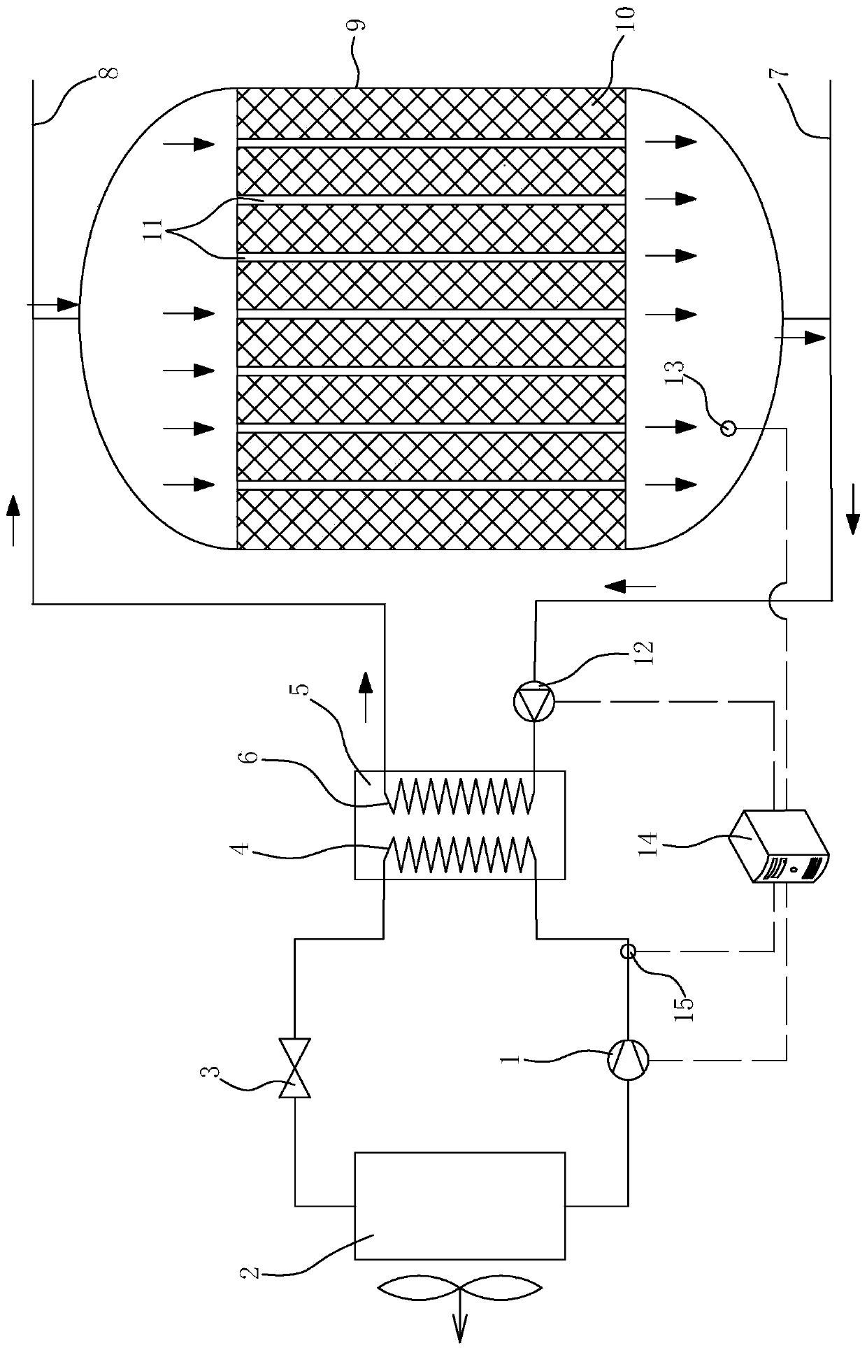
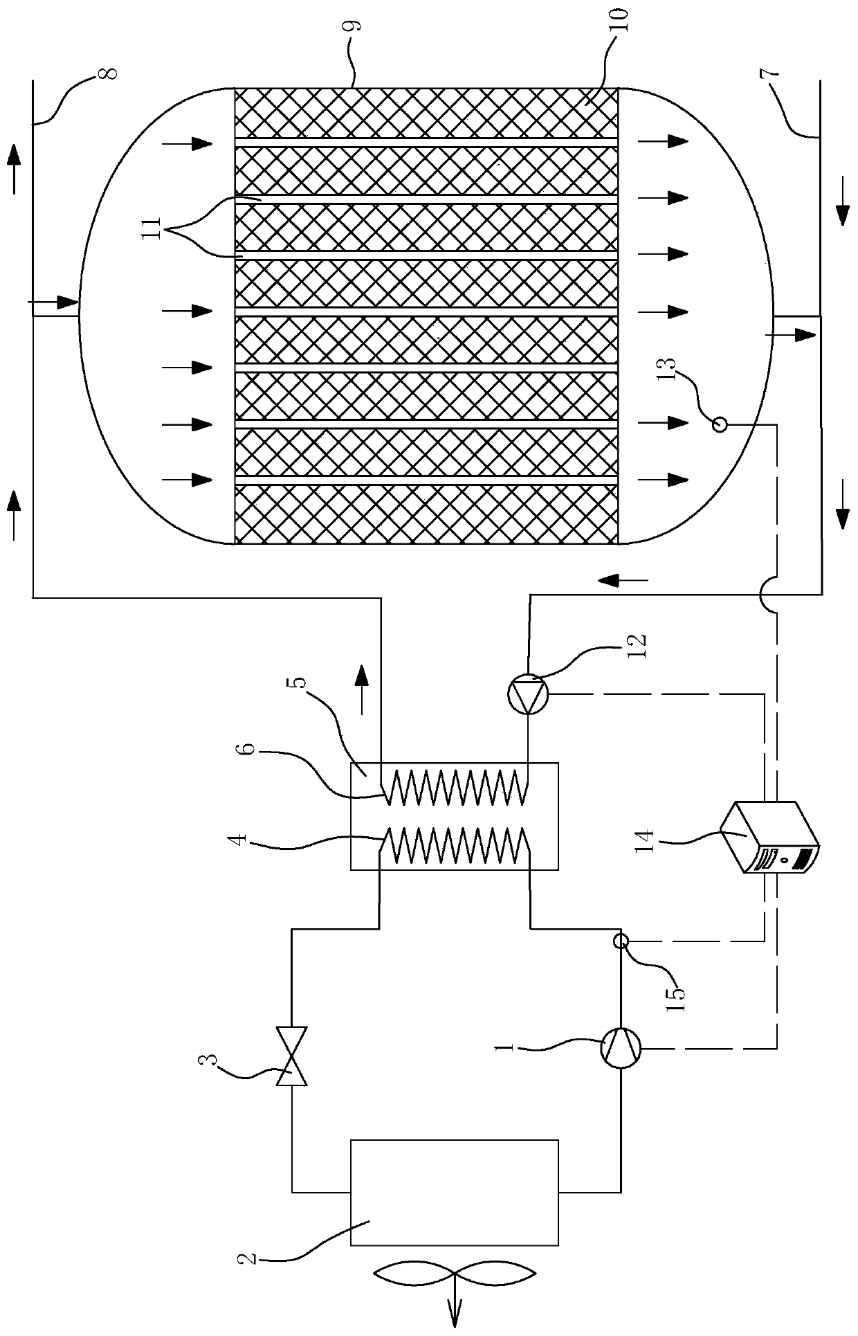
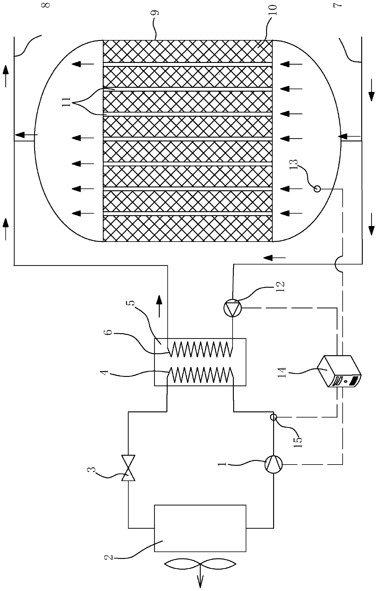
[0021] The air source heat pump heating system with phase change heat storage includes inverter compressor 1, evaporator 2, expansion valve 3, refrigerant side 4, condenser 5 and water side 6, starting from the exhaust pipe of inverter compressor 1 in sequence Connect the refrigerant side 4-expansion valve 3-evaporator 2, the outlet of the evaporator 2 is connected to the inlet of the inverter compressor 1, the refrigerant side 4 and the water side 6 are encapsulated in the condenser 5, and one end of the water side 6 is connected to the municipal water pipe 7. The other end is connected to the user water pipe 8, and a phase change heat storage device 9 is connected in parallel between the municipal water pipe 7 and the user water pipe 8, and a phase change heat storage material 10 is arranged in the phase change heat storage device 9, and the phase change heat storage The material 10 is provided with a plurality of heat...


PUM


Abstract

The invention discloses a heat supply system of an air source heat pump for phase change heat storage. A refrigerant side-an expansion valve-an evaporator are connected to a compressor outlet pipelinein sequence; the refrigerant side and a water side are sealed in a condenser; one end of the water side is connected to a municipal water pipe, and the other end is connected to an user water pipe; aphase change heat storer with a phase change heat storage material inside is connected between the municipal water pipe and the user water pipe in parallel; multiple heat exchange pipes are arrangedin the phase change heat storage material; one ends of the heat exchange pipes are connected to the municipal water pipe, and the other ends are connected to the user water pipe; a variable flow waterpump is disposed on a pipeline of the water side; a temperature sensor is disposed on the side, towards the municipal water pipe, in the phase change heat storer; a refrigerant pressure sensor is disposed in a compressor exhaust pipe; the temperature sensor and the refrigerant pressure sensor are in signal connection with the variable flow water pump through a computer system; and under cooperation of a temporary heat storage function of the phase change heat storage material and an instant heating function of the water side, heat generated by the heat pump system is utilized more reasonably.

Description

Technical field: [0001] The invention relates to the technical field of heat pumps, in particular to an air source heat pump heating system for phase change heat storage and a logic control method thereof. Background technique: [0002] The traditional heat pump heating system has been developed to a new technical level. At present, the heat pump heating system with relatively advanced technology uses phase change heat storage materials to temporarily store the heat produced by the heat pump, and can be released from the phase change heat storage materials for use when needed. At present, there are two main ways of using phase change heat storage technology to realize heating. [0003] One is that the heat obtained by heat pump heating is stored in the phase change heat storage material, and then when it needs to be used, the cold water flows through the phase change heat storage material, and the cold water is heated only by the phase change heat storage material. This tec...

Claims


Application Information

Patent Timeline
IPC IPC(8): F25B30/06F25B41/06F25B49/02F25B41/31
CPCF25B30/06F25B49/02F25B2400/24F25B2600/13F25B2700/21F25B41/31Y02B30/70
Inventor 梁守棋
Owner 佛山市恺庭科技有限公司
Why Eureka
Try Eureka