Vacuum cleaner assembly

A technology of vacuum cleaners and components, applied in the installation of vacuum cleaners, household appliances, electrical equipment, etc.

Active Publication Date: 2020-07-07
AB ELECTROLUX
View PDF7 Cites 1 Cited by
  • Summary
  • Abstract
  • Description
  • Claims
  • Application Information

AI Technical Summary

Problems solved by technology

Users will view both situations negatively

Method used


Image

  • Vacuum cleaner assembly
  • Vacuum cleaner assembly
  • Vacuum cleaner assembly

Examples


Embodiment Construction

[0039] Various aspects of the invention will now be described more fully. Like reference numerals refer to like elements throughout. Well-known functions or constructions will not necessarily be described in detail for brevity and / or clarity.

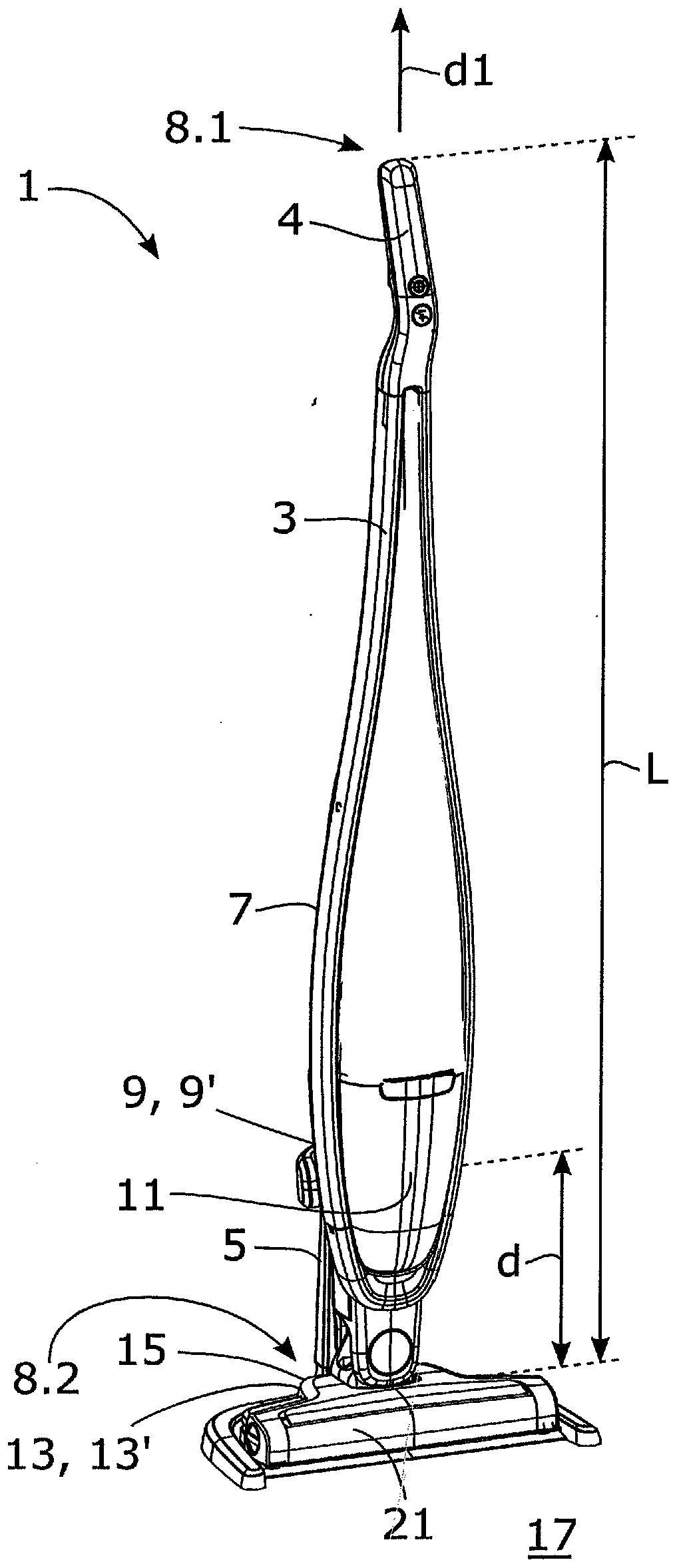
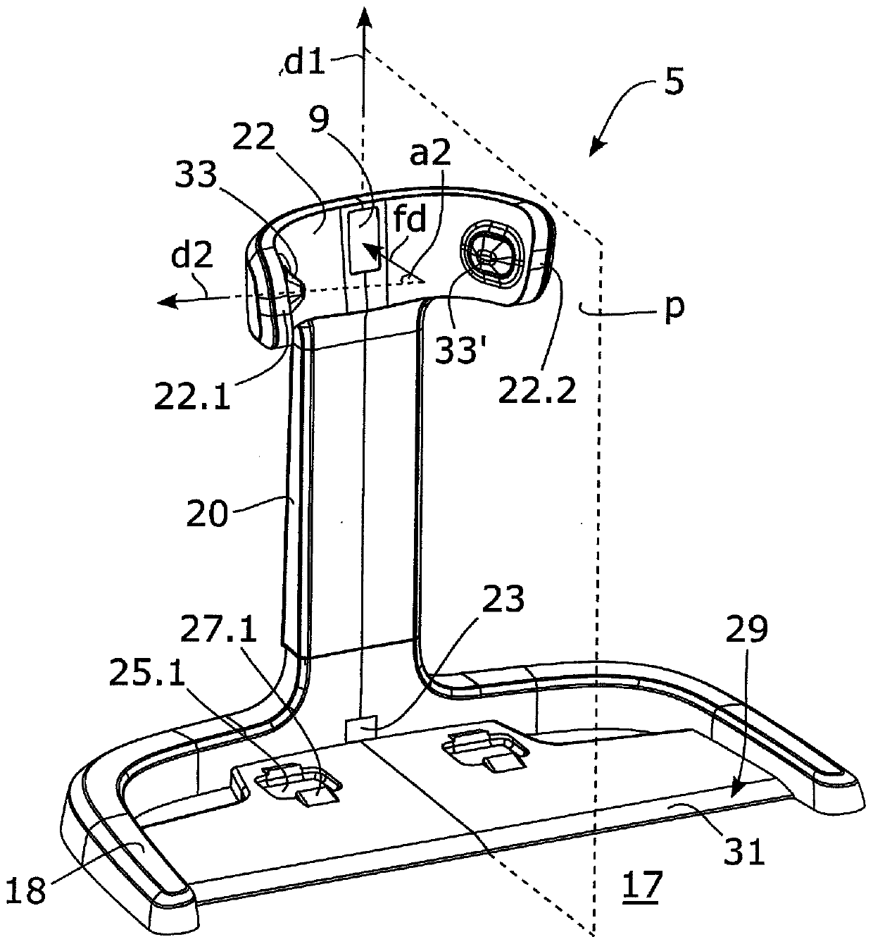
[0040] figure 1 A vacuum cleaner assembly 1 according to some embodiments is shown. The vacuum cleaner assembly 1 comprises a rechargeable stick vacuum cleaner 3 and a charging stand 5 . For brevity and / or clarity, the rechargeable stick vacuum cleaner 3 is referred to as "vacuum cleaner 3" in certain places herein. The vacuum cleaner 3 comprises an elongated body 7, a handle portion 4 arranged at a first end 8.1 of the elongated body 3, and a floor cleaning nozzle 21 arranged at a second end 8.2 of the elongated body 3. The vacuum cleaner 3 also includes a rechargeable battery, an electric motor and an impeller. For brevity and / or clarity, these parts are in the figure 1 Not indicated in . The electric motor is configured to dri...


PUM


Abstract

A vacuum cleaner assembly (1) is disclosed comprising a rechargeable stick type vacuum cleaner (3), and a charging dock (5). The vacuum cleaner (3) comprises an elongated body (7). The vacuum cleaner(3) is configured to be releasably positioned in the charging dock (5) such that the elongated body (7) extends along a first direction (d1). The assembly (1) further comprises a magnetic assembly (9,9') configured to fixate a first portion (11) of the vacuum cleaner (3) to the charging dock (5), and a second fixating assembly (13, 13') configured to fixate a second portion (15) of the vacuum cleaner (3) to the charging dock (5). The second portion (15) is arranged a distance (d) from the first portion (11) along the first direction (d1).

Description

technical field [0001] The present invention relates to a vacuum cleaner assembly comprising a rechargeable stick vacuum cleaner and a charging stand. Background technique [0002] Rechargeable stick vacuum cleaners have become increasingly popular. The reason for this may be that they are easy to use, require no power cords and require little space when not in use. Rechargeable stick vacuum cleaners are often sold with a charging stand in which the rechargeable stick vacuum cleaner can be releasably positioned when not in use. The charging stand includes a power cord configured to connect to an electrical outlet. The charging stand further includes electrical contact units configured to abut against the electrical contact units of the rechargeable stick vacuum cleaner when the rechargeable stick vacuum cleaner is positioned in the charging stand. [0003] There are some problems with vacuum cleaner assemblies that include rechargeable stick vacuum cleaners and charging d...

Claims


Application Information

Patent Timeline
Patent Type & Authority Applications(China)
IPC IPC(8): A47L5/24A47L9/28A47L9/00
CPCA47L5/24A47L9/0063A47L9/2873
Inventor J·瓦德柳斯F·奥斯特
Owner AB ELECTROLUX
Why Eureka
Try Eureka