Backlight module preparation process and backlight module

A technology of backlight module and preparation process, which is applied to mirrors, instruments, identification devices, etc., can solve the problems of poor dark line elimination effect, etc., and achieve the effects of good adjustability, high controllability and simplified process flow

Pending Publication Date: 2021-09-28
SHENZHEN REFOND OPTOELECTRONICS
View PDF0 Cites 0 Cited by
  • Summary
  • Abstract
  • Description
  • Claims
  • Application Information

AI Technical Summary

Problems solved by technology

[0005] In order to solve the technical problem of poor dark line elimination effect existing in backlight products in the prior art, an embodiment of the present invention provides a backlight module manufacturing process and a backlight module

Method used


Image

  • Backlight module preparation process and backlight module
  • Backlight module preparation process and backlight module
  • Backlight module preparation process and backlight module

Examples


Embodiment 1

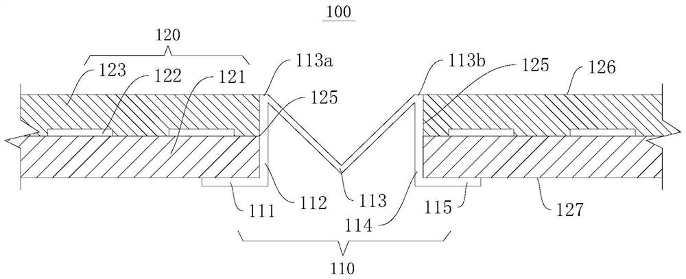
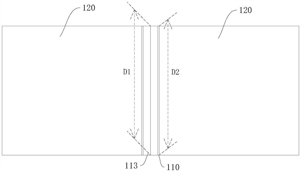
[0047] Please refer to figure 1 and figure 2 , this embodiment provides a backlight module 100 , the backlight module 100 is formed by splicing a plurality of light emitting modules 120 . The backlight module 100 includes: a reflective material 110 and a light emitting module 120 . The light emitting module 120 defines a light emitting surface 126 and a backlight surface 127 opposite to each other, and a side surface 125 connecting the light emitting surface 126 and the backlight surface 127 .

[0048] Wherein, the light-emitting modules 120 are spliced ​​together, and there is a seam between the light-emitting modules 120. The reflective material 110 is structured in a layered shape and is used to block the seam between the light-emitting modules 120. The reflective material 110 is arranged on two adjacent light-emitting modules. between the groups 120 and connected to the backlight surface 127 and / or the side surface 125 of the light emitting module 120 , so as to cover t...

Embodiment 2

[0065] Please refer to Figure 8 , this embodiment provides a backlight module 200 , the backlight module 200 is formed by splicing a plurality of light emitting modules 230 . The backlight module 200 includes: a backplane 210 , a reflective material 220 , a light emitting module 230 and a support 240 . The light emitting module 230 defines a light emitting surface 234 and a backlight surface 235 opposite to each other, and a side surface 236 connecting the light emitting surface 234 and the backlight surface 235 .

[0066] The support 240 is installed on the backplane 210, and the light-emitting module 230 is also installed on the backplane 210 and spliced ​​on the backplane 210. The support 240 is arranged between two adjacent light-emitting modules 230, and the reflective material 220 is covered on the support. 240 is close to the side of the light-emitting surface 126 of the light-emitting module 230 to cover the seams between the light-emitting modules 230 .

[0067] Wi...

Embodiment 3

[0083] Please refer to Figure 10 , this embodiment provides a backlight module 300. Compared with the backlight module 100 in Embodiment 1, the difference is that: the two adjacent light-emitting modules 310 in the backlight module 300 are provided with reflective materials 320. In a light-emitting module 310 , the reflective material 320 is disposed between the substrate 311 and the optical protective adhesive layer 312 to connect the light-reflective material 320 to the light-emitting module 310 , and the reflective material 320 extends toward another light-emitting module 310 . The reflective material 320 of two adjacent light-emitting modules 310 partially overlaps in the seam of the two light-emitting modules 310 , so as to cover the seam of the two light-emitting modules 310 .


PUM


Abstract

The invention discloses a backlight module preparation process and a backlight module, and relates to the field of backlight devices. The backlight module preparation process comprises the following steps: providing a reflective material and a light-emitting module, wherein the light-emitting module defines a light-emitting surface and a backlight surface which are opposite to each other, and a side surface connecting the light-emitting surface and the backlight surface; connecting the reflecting material to the backlight surface and / or the side surface of the light-emitting module; and splicing the light-emitting modules, so that splicing seams between the light-emitting modules are shielded and / or filled with the light-reflecting materials. Compared with a traditional mode, the controllability and the adjust-ability are good, the shielding condition of the light-reflecting material can be controlled, and the light-reflecting material can play a better shielding effect. The backlight module is prepared through the backlight module preparation process, so that the light-reflecting material can fully shield or fill the splicing seams between the light emitting modules, the situation of partial shielding / insufficient filling is avoided, the probability of dark lines or dark spots is greatly reduced, and the light emitting effect and the light emitting uniformity are effectively improved.

Description

【Technical field】 [0001] The invention relates to the field of backlight devices, in particular to a preparation process of a backlight module and the backlight module. 【Background technique】 [0002] At present, large-sized backlight products are composed of multiple backlight panels. After the preparation, there are joints between the backlight panels. In terms of display effect, dark lines are prone to appear at the joints, resulting in uneven light emission on the entire surface. [0003] Although there are many methods for eliminating dark lines at present, the effect of eliminating dark lines is generally not good. [0004] In view of this, this application is proposed. 【Content of invention】 [0005] In order to solve the technical problem of poor dark line elimination effect in backlight products in the prior art, an embodiment of the present invention provides a backlight module manufacturing process and a backlight module. [0006] An embodiment of the present ...

Claims


Application Information

Patent Timeline
Patent Type & Authority Applications(China)
IPC IPC(8): G09F9/30G02B5/08
CPCG09F9/30G02B5/08
Inventor 朱剑飞李幸达韩婷婷
Owner SHENZHEN REFOND OPTOELECTRONICS
Why Eureka
Try Eureka